
Autoclave Engineers Adapters/Couplings ��ͷ
��1945�꿪ʼ��Autoclave Engineers��ʼ�������а�ȫ���ɿ������Եĸ�ѹ��ϵͳ�����ǿ��������ڸ����¶ȡ�ѹ���ͻ���״�������죬AutoclaveEngineers�Ѿ���չ��Ϊ�����ѹ��ҵ�ṩ�ɿ��ĸ�ѹ������ͷ���ӵ����������ߡ���Ʒ������Autoclave Engineers�Կͻ��ij�ŵ��Autoclave�ķ�����ͷ���������ϸ�ı�������ѹ�����Դ�0��150,000 psi(10343 bar) ���¶ȴ� 0 �� 1200��F (650��C)����ǧ�ֱ仯��û�б�Ĺ����ܱ�Autoclave Engineers�ڸ�ѹҪ�������ø��ã�Ҳû�б�Ĺ����ܱ�Autoclave Engineers����ϵͳ���ɿ��;��д��µ����ԡ�Autoclave Engineers�IJ�ƷΪ����ͻ��ĸ����������ƣ����Ҿ���Ʒ�ʸߣ�����ʱ���۸��ʵ����ص���
AUTOCLAVE��Ʒ�����뷧 �� ��ȫ�� �DZ��� ���Ƶķ��ͷ��� ����ִ���� ��ͷ �ȵ�ż ѹ����
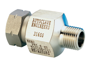
Autoclave Engineers Adapters/Couplings ��ͷ:
ѹ����0.055��1.4 bar����150,000 psi (10343 bar)
�¶ȣ�-423��F (-252��C)��1200��F (650��C)
���ӳߴ磺1/16����1-5/16���Ĺ��⾶
���ʣ�316�����
Valves, Fittings, and Tubing Catalog
Autoclave��ѹ��ͷ
Autoclave��ѹ��ͷ-�й��ܴ�������ϸ������
Autoclave��ѹ��ͷ������
�����ѹ����1034.3 MPa
�����¶ȷ�Χ��-423�H(-252��) ��1200�H(649��)
���ӳߴ磺1/16����1��
���ʣ�316SS
AutoclaveEngineers��˾���������������ȵĸ�ѹ������ͷ���Ӷ�������ѹ�����Դ�0��150,000 psi(10342 bar)���¶ȴ�-423��F(-252��C)��1200��F(649��C)��û�б�Ĺ����ܱ�Autoclave Engineers�ڸ�ѹҪ�������ĸ��ã�Ҳû�б�Ĺ����ܱ�AutoclaveEngineers����ϵͳ���ɿ��������д��µ����ԡ�
Autoclave��ѹ���ţ���ѹ�뷧����ѹ����ȫ�����DZ��������Ƶķ��ͷ��顢��ͷ�����ӡ�ѹ�������ȵ�ż������ִ������
Ӧ������:�����;�.ʯ�ͻ�������������.
Autoclave��ѹ��ͷ�ͺ�
Male/Female Adapters
15M92R1 6M94R2 6M96R2 4M98R2 15M94R6 15M96R615M99R6 15M94R3 15M96R3 15M99R3
10M92R8 10M94R8 10M96R8 10M98R815M72E1 6M74E2 6M76E2 4M78E2 15M74E6 15M76E6
15M79E6 15M74E315M76E3 15M79E3 10M72E8 10M74E8 10M76E8 10M78E8 15M92E1
6M94E26M96E2 4M98E2 15M94E6 15M96E6 15M99E6 15M912E6 15M94E3 15M96E310M92E8
10M94E8 10M96E8 10M98E8 10M912E8 10M916E8 15M122E1 6M124E26M126E2 4M128E2
15M124E6 15M126E6 15M129E6 15M1212E6 15M1216E615M124E3 15M126E3 15M129E3
10M122E8 10M124E8 10M126E8 10M128E810M1212E8 10M1216E8 43M164B3 43M166B3
43M169B3 43M169B40 15M42B16M44B2 6M46B2 4M48B2 20M44B6 20M46B6 20M49B6 20M412B6
43M416B360M45B3 60M46B3 60M49B3 15M42B8 15M44B8 15M46B8 15M48B8 10M412B86M54B2
6M56B2 4M58B2 20M54B6 20M56B6 20M59B6 20M512B6 60M54B360M56B3 60M59B3 15M58B8
10M512B8 15M62B1 6M64B2 6M66B2 4M68B220M64B6 20M66B6 20M69B6 20M612B6 20M616B6
43M616B6 60M64B3 60M65B360M69B3 15M62B8 15M64B8 15M66B8 15M68B8 10M612B8
10M616B8 15M92B16M94B2 6M96B2 4M98B2 20M94B6 20M96B6 20M99B6 20M912B6
20M916B643M916B3 60M94B3 60M95B3 60M96B3 15M92B8 15M94B8 15M96B8
15M98B810M912B8 10M916B8 20M912G6 15M98G8 15M22N1 15M24N2 15M26N2
10M28N215M24N6 15M26N6 15M29N6 15M24N3 15M26N3 15M29N3 15M42N1 15M44N215M46N2
10M48N2 15M44N6 15M46N6 15M49N6 15M412N6 15M416N6 15M424N615M44N3 15M45N3
15M46N3 15M49N3 15M48N8 15M62N1 15M64N2 15M66N210M68N2 15M64N6 15M66N6 15M69N6
15M612N6 15M616N6 15M64N3 15M66N315M69N3 15M69N40 10M68N8 15M82N1 15M84N2
15M86N2 10M88N2 15M84N615M86N6 15M89N6 15M812N6 15M816N6 15M84N3 15M86N3 15M89N3
15M89N4010M812N8 10M124N2 10M126N2 10M128N2 10M124N6 10M126N6 10M129N610M1212N6
10M1216N6 10M124N3 10M126N3 10M129N3 10M122N8 10M166N210M168N2 10M166N6 10M169N6
10M1612N6 10M1616N6 10M166N3 10M169N310M168N8 6M24C2 6M26C2 4M28C2 6M24C6 6M26C6
6M29C6 6M24C3 6M26C36M29C3 15M22C8 15M24C815M26C8 15M28C8 15M224C6 6M42D1 6M46D2
4M48D26M44D6 6M46D6 6M49D6 6M412D6 6M44D3 6M46D3 6M49D3 15M42D8 15M44D815M46D8
15M48D8 10M412D8 6M62D1 6M64D2 4M68D2 6M64D6 6M66D6 6M69D66M612D6 6M616D6 6M64D3
6M66D3 6M69D3 15M62D8 15M64D8 15M66D815M68D8 10M612D8 10M616D8 15M624D6 4M82D1
4M84D2 4M86D2 4M84D64M86D6 4M89D6 4M812D6 4M816D6 4M84D3 4M86D3 4M89D3 10M82D8
10M84D810M86D8 10M88D8 10M812D8 10M816D8 15MX42K1 6MX44K2 6MX46K2
4MX48K220M46K6 20M49K6 20M412K6 20M416K6 20M44K3 20M45K3 20M46K3
20M49K315MX42K8 15MX44K8 15MX46K8 15MX48K8 10MX412K8 15MX62K1 6MX64K26MX66K2
4MX68K2 20M64K6 20M69K6 20M612K6 20M616K6 20M64K3 20M65K320M66K3 20M69K3
15MX62K8 15MX64K8 15MX66K8 15MX68K8 10MX612K810MX616K8 15MX92K1 6MX94K2 6MX96K2
4MX98K2 20M94K6 20M96K6 20M912K620M916K6 20M94K3 20M95K3 20M96K3 20M99K3
15MX92K8 15MX94K8 15MX96K815MX98K8 10MX912K8 10MX916K8 6MX124K2 6MX126K2
4MX128K2 20M124K620M126K6 20M129K6 20M1216K6 20M124K3 20M125K3 20M126K3
20M129K320M129K40 15MX124K8 15MX126K8 15MX128K8 10MX1212K8 10MX1216K86MX162K2
6MX164K2 6MX166K2 4MX168K2 20M164K6 20M166K6 20M169K620M1612K6 20M164K3 20M166K3
20M169K3 15MX164K8 15MX166K8 15MX168K810MX1612K8 10MX1616K8 15M244K6
Couplings
60F4433 60F4633 60F4933 60F4533 43F4163360F6633 60F6933 60F6533
20FX4466 20F4666 20F4966 20F41266 20F4166620F4463 20F4663 20F4963 20F4563
20F41663 20FX6666 20F6966 20F6126620F61666 20F6463 20F6663 20F6963 20F6563
20F61663 20FX9966 20F9126620F91666 20F9463 20F9663 20F9963 20F9563 20FX12
20F121666 20F1246320F12663 20F12963 20F12563 20FX16 20F16463 20F16663
20F1696320F16563 15F221 6F2412 6F2612 4F2812 15F2416 15F2616 15F291615F21616
15F2413 15F2613 15F2913 6F4422 6F4622 4F4822 6F4426 6F46266F4926 6F4423 6F4623
6F4923 6F6622 4F6822 6F6426 6F6626 6F69266F61226 6F61626 6F6423 6F6623 6F6923
4F8822 4F8426 4F8626 4F89264F81226 4F81626 4F8423 4F8623 4F8923 15F2281 15F2482
15F268210F2882 15F2486 15F2686 15F2986 15F21286 15F2483 15F2683 15F298315F2583
15F4281 15F4482 15F4682 10F4882 15F4486 15F4686 15F498615F41286 15F41686 15F4483
15F4683 15F4983 15F4583 15F6281 15F648215F6682 10F6882 15F6486 15F6686 15F6986
15F61286 15F61686 15F648315F6683 15F6983 15F6583 15F8281 15F8482 15F8682 10F8882
15F848615F8686 15F8986 15F81286 15F81686 15F8483 15F8683 15F8983
15F858310F12882 10F12686 10F12986 10F121286 10F121686 10F12983
10F1698610F161686 10F16483 10F16983
43F61633 60F9933 40F9933 60F9533 43F91633150F5533 43F16 15M249K6 15M2412K6
15M2416K6 60F4433 60F4633 60F493360F4533 43F41633 60F6633 60F6933 60F6533
43F61633 60F9933 40F993360F9533 43F91633 150F5533 43F16 0F4433 60F4633 60F4933
60F453343F41633 60F6633 60F6933 60F6533 43F61633 60F9933 40F9933
60F953343F91633 150F5533 43F16 15MFAP6J6
Male/Male Adapters
15MAL2L2 15MAL2L4 15MAL4L4 10MAL8L810MAL6L8
15MAP4RH9 15MAP4RH12 15MAP4RH16 15MAP6RH915MAP6RH12 15MAP6RH16 15MAP8RH9
15MAP8RH12 15MAP8RH14 15MAP8RH1610MAP12RH12 10MAP12RH16 10MAP16RH16 10MAP12RH21
10MAP16RH2110MAP16RH9 26MARH9RH16 26MARH12RH16 26MARH16RH16
30MARH9RH1230MARH12RH12 40MARH9RH9 20MARH21RH21 26MAH4RH16 26MAH6RH1626MAH9RH16
30MAH4RH12 30MAH6RH12 30MAH9RH12 40MAH4RH9 40MAH6RH940MAH9RH9 20MAM4RH9
20MAM4RH12 20MAM4RH16 20MAM6RH9 20MAM6RH1220MAM6RH16 20MAM9RH9 20MAM9RH12
20MAM9RH14 20MAM9RH16 20MAM12RH920MAM12RH12 20MAM12RH16 20MAM12RH21 20MAM16RH9
20MAM16RH1220MAM16RH14 20MAM16RH16 20MAM16RH21 20MAM9RH21 15MAP4P4
15MAP4P615MAP4P8 15MAP6P6 15MAP6P8 15MAP8P8 15MAP4P4 15MAP4P6 15MAP4P815MAP6P6
15MAP6P8 15MAP8P8 15MAH4P4 15MAH4P6 15MAH4P8 15MAH6P415MAH6P6 15MAH6P8 15MAH9P4
15MAH9P6 15MAH9P8 15MAM4P4 15MAM4P615MAM4P8 15MAM6P4 15MAM6P6 15MAM6P8 15MAM9P4
15MAM9P6 15MAM9P815MAM12P4 15MAM12P6 15MAM12P8 15MAM16P4 15MAM16P6
15MAM16P810MAM9P16 10MAM12P12 10MAM12P16 10MAM16P16 10MAM9P12 15MAL2P215MAL2P4
15MAL4P2 15MAL6P4 10MAL8P6 15MAL2P8 15MAL4P8 15MAL6P810MAL8P12 10MAL8P8 40MAH9H9
60MAH4H4 60MAH4H5 60MAH4H6 60MAH4H960MAH5H6 60MAH6H6 60MAH6H9 60MAH9H9 150MAH5H5
20MAM4M4 20MAM4M620MAM4M9 20MAM4M12 20MAM4M16 20MAM6M6 20MAM6M9 20MAM6M12
20MAM6M1620MAM9M9 20MAM9M12 20MAM9M16 20MAM12M12 20MAM12M16 20MAM16M420MAM4M4
20MAM4M6 20MAM4M9 20MAM4M12 20MAM4M16 20MAM6M6 20MAM6M920MAM6M12 20MAM6M16
20MAM9M9 20MAM9M12 20MAM9M16 20MAM12M1220MAM12M16 20MAM16M4 20MAM16M16 15MAL2H4
10MAL2H6 15MAL4M410MAL8M9
QSSϵ�и�ѹ��ͷ
15MAQ6P415MAQ9H415MAQ4RH9 15MAQ6RH9 15MAQ9RH9 15MAQ9RH12 15MAQ9RH16
15M44NQ15M46NQ 15M64NQ 15M66NQ 15M69NQ 15M84NQ 15M86NQ 15M89NQ 10M129NQ10M1212NQ
10M169NQ 10M1612NQ 15M812NQ 15M44BQ 15M46BQ 15M94BQ15M96BQ 15M99BQ 15M66BQ
15M912BQ 15M64KQ 15M66KQ 15M612KQ 15M94KQ15M96KQ 15M99KQ 15M912KQ 15M1212KQ
15M169KQ 15M1612KQ 15M49KQ15M44KQ 15M46KQ 15M64QQ 15M94QQ 15M96QQ 15M126QQ
15M129QQ 15M49QQ15M612QQ 15M912QQ 15M124QQ 15M44Q8 15M64Q8 15M66Q8 15M68Q8
15M94Q815M96Q8 15M98Q8 15M128Q8 15MFAP6J6
Male/Male JIC Adapters
20MAJ6J6 20MAJ4J4 20MAJ6J8 20MAJ8J8 20MAH4J420MAH4J6 20MAH4J8 20MAH6J4 20MAH6J6
20MAH6J8 20MAH9J4 20MAH9J620MAH9J8 20MAH4J10 20MAH4J2 15MAM4J12 15MAM6J12
15MAM9J1215MAM12J12 15MAM12J16 15MAM16J12 15MAM16J16 20MAM4J4 20MAM4J620MAM4J8
20MAM6J4 20MAM6J6 20MAM6J8 20MAM9J4 20MAM9J6 20MAM9J820MAM9J10 20MAM12J4
20MAM12J6 20MAM12J8 20MAM16J4 20MAM16J620MAM16J8 15MAM4J16 15MAM6J16
15MAM9J1615MAL4J4
15MAP4J4 15MAP4J6 15MAP4J8 15MAP4J12 15MAP6J415MAP6J6 15MAP6J8 15MAP6J12
15MAP8J4 15MAP8J8 15MAP8J12
Male/Female JIC Adapters
20MFAH4J4 20MFAM4J4 20MFAM4J6 20MFAJ12J415MFAJ4P4 15MFAJ4P8 20MFAJ4H4 20MFAJ4H6
20MFAJ4H9 20MFAJ6H620MFAJ4M4 20MFAJ4M6 20MFAJ4M9 20MFAJ4M12 20MFAJ4M16
20MFAJ6M420MFAJ6M6 20MFAJ6M9 20MFAJ6M12 20MFAJ6M16 20MFAJ8M4 20MFAJ8M620MFAJ8M9
20MFAJ8M12 20MFAJ8M16 15MFAJ12M4 15MFAJ12M6 15MFAJ12M915MFAJ12M12 15MFAJ12M16
15MFAJ16M4 15MFAJ16M6 15MFAJ16M915MFAJ16M12 15MFAJ16M16 20MFAJ4M4 20MFAJ4M6
20MFAJ4M9 20MFAJ4M1220MFAJ4M16 20MFAJ6M4 20MFAJ6M6 20MFAJ6M9 20MFAJ6M12
20MFAJ6M1620MFAJ8M4 20MFAJ8M6 20MFAJ8M9 20MFAJ8M12 20MFAJ8M16
15MFAJ12M415MFAJ12M6 15MFAJ12M9 15MFAJ12M12 15MFAJ12M16 15MFAJ16M4
15MFAJ16M615MFAJ16M9 15MFAJ16M12 15MFAJ16M16
Bulkheadϵ��
20BAMJ4FH420BAMJ6FH4 20BAMJ4FM4 20BAMJ4FM6 20BAMJ6FM4 20BAMJ6FM6
20BAMJ6FM920BAMJ8FM6 20BAMJ8FM9 20BAMJ8FM12 20BAMJ4FM12 20BAMJ6FM1220BAMJ8FM16
15BAMJ4FL4 15BAMP6FM6 15BAMP4FM4 15BAMP4FM640BAMRH9FH4 40BAMRH9FH9 30BAMRH12FH9
20BAMRH9FM6 20BAMRH9FM920BAMRH12FM9 20BAMRH12FM16 20BAMRH16FM16 20BAMRH9FM4
SAE O-Ring Adapters
M44MC2B M46MC2B M44MC3B M46MC3B M64MC3BM66MC3B M24MC6B M26MC6B M44MC6B M46MC6B
M49MC6B M64MC6B M66MC6BM69MC6B M86MC6B M89MC6B M812MC6B M1012MC6B M1016MC6B
M126MC6BM1212MC6B M1216MC6B M1616MC6B
Needle Valves . Low Pressure to 11,500 psi (793 bar) . Medium Pressure to 20,000 psi (1379 bar) . High Pressure to 150,000 psi (10342 bar) . Mini Valves to 15,000 psi (1034 bar) . Micrometering Valves . Block and Bleed Valves . Extreme Temperature Valves . Diverter Valves . Yoke Valves . Valve Options Valve Actuators . Piston . Diaphragm . Solenoid Packages Fittings and Tubing . Low Pressure to 15,000 psi (1034 bar) . Elbows, Tees & Crosses . Straight and Bulkhead Couplings . Tubing . Filter / Check Valves . Medium Pressure to 20,000 psi (1379 bar) . Elbows, Tees & Crosses . Straight, Union and Bulkhead Couplings . Tubing & Nipples . Filter / Check Valves . Anti-Vibration Collet and Gland Assembly . High Pressure to 150,000 psi (10342 bar) . Elbows, Tees & Crosses . Straight, Union and Bulkhead Couplings . Tubing & Nipples . Filter / Check Valves . Anti-Vibration Collet and Gland Assembly Adapters / Couplings . Couplings . Male / Female . Male/Male . Male/Male JIC/BSP . EZ-Union . Header Couplings . Bulkhead . Tube Caps & Gauge Connectors Ball Valves . 2-Way . 3-Way . 4-Way . Subsea . Actuators . Options/Details Relief Valves . Metal Seat . Soft Seat Custom Valves & Manifold . Special Connection Valves . NPT Valves . Bottle Valves . Custom Valves and Special Materials . Manifold Blocks . Clamp Style Manifolds Accessories . Thermocouples . Safety Heads / Rupture Discs . Gauges Sour Service Products . General information . Well Head Gauge and Bleed Valves . Stem Valves . Fittings and Tubing . Check Valves and Adapters . Servere Service Valves . Gauges Metric Series . Valves . Valves Actuators . Fittings . Tubing and Nipples . Safety Head Assembly and Rupture Discs . Manual Coning & Threading Tools . Gauges Instrumentation Valves
.
5000 Series Needle / Gauge Valves
.
5000 Series Manifold Valves
Tools, Installation, Operation & Maintenance . Low Pressure Connection Installation . Manual Coning and Threading Tools . Medium and High Pressure Connection Installation . Anti-Vibration Collet Gland Assembly . Reseating Female Cone Seats . AEGCTM Coning and Threading Machine . Torque Wrench and Torque Adapters . Torque Values . Tube Connection Dimensions . Hydraulic Tube Bender . Lubrication Guide Technical Information . Technical and Application Information . Autofrettage and High Cycle Tubing . Medium & High-Pressure Connections . Pressure/Temperature Rating Guide . Material vs. Rating Curves . Flow Calculations and Liquid Flow Curves . Conversion Tables . Pressure vs. Bend Radius
ISO-9001
Certified
02-0100CE-0302
www.autoclaveengineers.com
Needle Valve
Index
Low Pressure Valves:
. 10V & SW Series, Pressures to 11,500 psi. (793 bar)
Medium Pressure Valves:
. SM Series, Pressures to 20,000 psi. (1379 bar)
(Note: SM Series replace existing SC Series)
High Pressure Valves:
. 30SC, 30VM, 40VM, 60VM, 100V, & 150V Series, Pressures to 150,000 psi. (10342 bar)
Mini Valves:
. MVE Series, Pressures to 15,000 psi. (1034 bar)
Micro Metering Valves: . VRMM Series, Pressures to 60,000 psi. (4137 bar) Block and Bleed Valves: . 20MVBB, Rated to 20,000 psi. (1379 bar) Extreme Temperture Valves: . HT, LT, & PV Series, Pressures to 60,000 psi. (4137 bar) Diverter Valves:
. 20DV Series, Pressures to 20,000 psi. (1379 bar)
Yoke Valves:
. 15Y, 43Y & 50Y Series, Pressures to 50,000 psi. (3447 bar)
Valve Options:
. Stem Types, Material Selection, Coatings and Handles
ISO-9001
Certified
Needle Valves
Low Pressure
10V & SW Series
Pressures to 11,500 psi (793 bar)
Since 1945 Autoclave Engineers has designed and built premium quality valves, fittings and tubing. This commitment to engineering and manufacturing excellence has earned Autoclave a reputation for reliable efficient product performance. Autoclave Engineers has long been established as the world leader in high pressure fluid handling components for the chemical/petrochemical, research, and oil and gas industries.
Low Pressure Valve Features:
.
10V Series valve design provides in-line tube connections for 1/4�� to 1/2�� tube sizes.
.
SW Series valve design provides increased flow capabilities.
.
Tubing sizes from 1/16�� to 1/2��.
.
Rising stem/barstock body design.
.
Non-rotating stem prevents stem/seat galling.
.
Metal-to-metal seating achieves bubble-tight shutoff, longer stem/seat life in abrasive flow, greater durability for repeated on/off cycles and excellent corrosion resistance.
.
PTFE (Teflon) encapsulated packing provides dependable stem and body sealing.
.
Stem sleeve and packing gland materials have been selected to achieve extended thread cycle life and reduced handle torque.
.
Choice of Vee or Regulating stem tips.
.
Available in five body patterns.
Autoclave valves are complemented by a complete line of low pressure fittings, tubing, check valves and line filters. The 10V and SW series use Autoclave��s SpeedBite connection. This single-ferrule compression sleeve connection delivers fast, easy make-up and reliable bubble-tight performance in liquid or gas service.
www.autoclaveengineers.com
Valve Series -10V Series
Pressures to 11,500 psi (793 bar)
All general terms and conditions of sale, including limitations of our liability, apply to all products and services sold.
Number of turns open
For complete information on available stem types, optional connections and additional valve options, see Needle Valve Options section or contact your Sales Representative. 10V Series valves are furnished complete with connection components, unless otherwise specified.
Vee stem (on-off service)
regulating stem (tapered tip for regulating and shutoff)
Tube Pres./Temp. Outside Rating Diameter Orifice psi (bar) Size Connection Size Rated @ Room Inches Type Inches (mm) Cv*Temperature**
1/8 W125 0.094 (2.39) 0.12 11,000 (758) 1/4 W250 0.125 (3.18) 0.20 11,500 (793) 3/8 W375 0.125 (3.18) 0.20 10,000 (690) 1/2 SW500 0.250 (6.35) 0.86 5,500 (379)
Notes: *CV values shown are for 2-way straight valve pattern. For 2-way angle patterns, increase CV value 50%. (Based on water) ** For complete temperature ratings see pressure/temperature rating guide in Technical Information section.
Generalized Flow Coefficient Curves (Cv)
7 6 5 4 3 2 1 0
% of rated Cv
To ensure proper fit use Autoclave tubing
Ordering Procedure
Typical catalog number: 10V4071 4 07
10V
1
Options
Valve Outside Diameter Stem/Seat Body Options Series Tube Size Type
Pattern
For extreme
1 -two-way straight
2-1/8�� 07 -non-rotating temperature and other
4-1/4��
2 -two-way angle options, see Valve 6-3/8�� 08 -non-rotating 3 -three-way, two on pressure Options.
8-1/2��
4 -three-way, one on pressure
5 -three-way, two stem
manifold valve
87 -Vee stem with replaceable Note: Contact Sales for 1/16��tube size or seat see MVE Series.
88 -Regulating stem with replaceable seat
Valve Options
Extreme Temperatures
Standard Autoclave valves with Teflon packing may be operated to 450��F (232��C). High temperature packing and/or extended stuffing box is available for service from 0��F (-17.8��C) to 650��F (343��C) by adding the following suffixes to catalog order number..TG standard valve with Teflon glass packing to 600��F (316��C). GY standard valve with graphite braided yarn packing to 650��F (343��C).
.Autoclave Engineers does not recommend compression sleeve connections below 0 �� F (-17.8 �� C) or above 650 �� F (343 �� C). For additional valve options, contact your Sales Representative.
Valve Maintenance
Repair Kits: add ��R�� to the front of valve catalog number for proper repair kit. (Example: R10V4071)
Valve Bodies: Valve bodies are available. Order using the eight (8) digit part number found on the valve drawing or contact your Sales Representative for information.
Consult your Autoclave representative for pricing on repair kits and valve bodies. Refer to the Tools, Installation, Operation and Maintenance section for proper maintenance procedures.
2-Way Straight
10V2071 VEE 1/8** 0.094 1.50 0.75 0.31 1.06 0.81 1.38 3.00 0.62 0.17 3.75 0.56 0.31 0.62 See Figure 1
10V2081 REG (3.18) (2.39) (38.10) (19.05) (7.87) (26.92) (20.57) (35.05) (76.20) (15.75) (4.32) (95.25) (14.22) (7.87) (15.75)
10V4071 VEE 1/4 0.125 2.00 1.00 0.56 1.19 1.69 3.00 0.97 0.22 4.44 0.69 0.38 1.00
10V4081 REG (6.35) (3.18) (50.80) (25.40) (14.22) (30.23) (42.93) (76.20) (24.64) (5.59) (112.78) (17.53) (9.65) (25.40)
10V6071 VEE 3/8 0.125 2.00 1.00 0.62 1.19 1.69 3.00 0.97 0.22 4.31 0.69 0.38 1.00
10V6081 REG (9.53) (3.18) (50.80) (25.40) (15.75) (30.23) (42.93) (76.20) (24.64) (5.59) (109.47) (17.53) (9.65) (25.40)
10V8071 VEE 1/2 0.250 2.50 1.25 0.53 1.25 1.81 3.00 0.97 0.22 4.44 0.69 0.38 1.00
10V8081 REG (12.70) (6.35) (63.50) (31.75) (13.46) (31.75) (45.97) (76.20) (24.64) (5.59) (112.78) (17.53) (9.65) (25.40)
2-Way Angle
10V2072 VEE 1/8 0.094 1.50 0.75 0.31 0.81 1.56 3.00 0.62 0.17 3.94 0.50 0.31 0.62 See Figure 2
10V2082 REG (3.18) (2.39) (38.1) (19.05) (7.87) (20.57) (39.62) (76.20) (15.75) (4.32) (100.08) (12.70) (7.87) (15.75)
10V4072 VEE 1/4 0.125 2.00 1.00 0.56 1.19 2.19 3.00 0.97 0.22 4.81 0.69 0.31 1.00
10V4082 REG (6.35) (3.18) (50.80) (25.40) (14.2) (30.23) (55.63) (76.20) (24.64) (5.59) (122.17) (17.53) (7.87) (25.40)
10V6072 VEE 3/8 0.125 2.00 1.00 0.62 1.19 2.19 3.00 0.97 0.22 4.81 0.69 0.31 1.00
10V6082 REG (9.53) (3.18) (50.80) (25.40) (15.7) (30.23) (55.63) (76.20) (24.64) (5.59) (122.17) (17.53) (7.87) (25.40)
10V8072 VEE 1/2 0.250 2.50 1.25 0.53 1.25 2.50 3.00 0.97 0.22 5.06 0.69 0.38 1.00
10V8082 REG (12.70) (6.35) (63.50) (31.75) (13.5) (31.75) (63.50) (76.20) (24.64) (5.59) (128.52) (17.53) (9.65) (25.40)
3-Way / 2 on Pressure
10V2073 VEE 1/8** 0.094 1.50 0.75 0.31 1.06 0.81 1.69 3.00 0.62 0.17 4.06 0.50 0.31 0.62 See Figure 3
10V2083 REG (3.18) (2.39) (38.10) (19.05) (7.87) (26.92) 20.57 (42.93) (76.20) (15.75) (4.32) (103.12) (12.70) (7.87) (15.75)
10V4073 VEE 1/4 0.125 2.00 1.00 0.56 1.19 2.19 3.00 0.97 0.22 4.81 0.69 0.38 1.00
10V4083 REG (6.35) (3.18) (50.80) (25.40) (14.22) (30.23) (55.63) (76.20) (24.64) (5.59) (122.17) (17.53) (9.65) (25.40)
10V6073 VEE 3/8 0.125 2.00 1.00 0.62 1.19 2.19 3.00 0.97 0.22 4.81 0.69 0.38 1.00
10V6083 REG (9.53) (3.18) (50.80) (25.40) (15.75) (30.23) (55.63) (76.20) (24.64) (5.59) (122.17) (17.53) (9.65) (25.40)
10V8073 VEE 1/2 0.250 2.50 1.25 0.53 1.19 2.44 3.00 0.97 0.22 5.06 0.69 0.38 1.00
10V8083 REG (12.70) (6.35) (63.50) (31.75) (13.46) (30.23) (61.98) (76.20) (24.64) (5.59) (128.52) (17.53) (9.65) (25.40)
G - Packing gland mounting hole drill size * H Dimension is with stem in closed position. For prompt service, Autoclave stocks
G1 - Bracket mounting hole size ** 1/8�� straight and 3-Way/2 on pressure valves have offset select products. Consult factory.
Panel mounting drill size: 0.22�� all valves. tube connections. All dimensions for reference only and subject to change.
3-Way / 1 on Pressure
10V2074 VEE 1/8 0.094 1.50 0.75 0.31 0.81 1.56 3.00 0.62 0.17 3.94 0.50 0.31 0.62 See Figure 4
10V2084 REG (3.18) (2.39) (38.1) (19.05) (7.87) (20.57) (39.62) (76.20) (15.75) (4.32) (100.08) (12.70) (7.87) (15.7)
10V4074 VEE 1/4 0.125 2.00 1.00 0.56 1.19 2.19 3.00 0.97 0.22 4.81 0.69 0.38 1.00
10V4084 REG (6.35) (3.18) (50.8) (25.40) (14.22) (30.23) (55.63) (76.20) (24.64) (5.59) (122.17) (17.53) (9.65) (25.40)
10V6074 VEE 3/8 0.125 2.00 1.00 0.62 1.19 2.19 3.00 0.97 0.22 4.81 0.69 0.38 1.00
10V6084 REG (9.53) (3.18) (50.8) (25.40) (15.75) (30.23) (55.63) (76.20) (24.64) (5.59) (122.17) (17.53) (9.65) (25.40)
10V8074 VEE 1/2 0.250 2.50 1.25 0.53 1.19 2.44 3.00 0.97 0.22 5.06 0.69 0.38 1.00
10V8084 REG (12.70) (6.35) (63.5) (31.75) (13.46) (30.23) (61.98) (76.20) (24.64) (5.59) (128.52) (17.53) (9.65) (25.40)
2-Way Angle / Replaceable Seat
10V2872 VEE 1/8 0.094 1.50 0.75 0.31 0.81 1.28 1.56 3.00 0.62 0.17 4.50 0.50 0.31 0.62 See Figure 5
10V2882 REG (3.18) (2.39) (38.10) (19.05) (7.87) (20.57) (32.51) (39.62) (76.20) (15.75) (4.32) (114.30) (12.70) (7.87) (15.75)
10V4872 VEE 1/4 0.125 2.00 1.00 0.56 1.12 2.13 2.25 3.00 0.97 0.22 6.00 0.69 0.38 1.00
10V4882 REG (6.35) (3.18) (50.80) (25.40) (14.22) (28.45) (54.10) (57.15) (76.20) (24.64) (5.59) (152.40) (17.53) (9.65) (25.40)
10V6872 VEE 3/8 0.125 2.00 1.00 0.62 1.12 2.28 2.25 3.00 0.97 0.22 6.00 0.69 0.38 1.00
10V6882 REG (9.53) (3.18) (50.80) (25.40) (15.75) (28.45) (57.91) (57.15) (76.20) (24.64) (5.59) (152.40) (17.53) (9.65) (25.40)
10V8872 VEE 1/2 0.250 2.50 1.25 0.53 1.00 2.50 2.38 3.00 0.97 0.28 6.06 0.69 0.38 1.00
10V8882 REG (12.70) (6.35) (63.50) (31.75) (13.46) (25.45) (63.50) (60.45) (76.20) (24.64) (7.11) (153.92) (17.53) (9.65) (25.40)
3-Way / 2-Stem Manifold
10V2075 VEE 1/8 0.094 1.50 0.75 0.31 1.12 0.81 2.25 3.00 0.62 0.17 4.63 0.50 0.31 0.62 See Figure 6
10V2085 REG (3.18) (2.39) (38.10) (19.05) (7.87) (28.45) (20.57) (57.15) (76.20) (15.75) (4.32) (117.60) (12.70) (7.87) (15.7)
10V4075 VEE 1/4 0.125 2.00 1.00 0.56 1.69 1.09 3.38 3.00 0.97 0.22 5.82 0.69 0.38 1.00
10V4085 REG (6.35) (3.18) (50.80) (25.40) (14.22) (42.93) (27.69) (85.85) (76.20) (24.64) (5.59) (147.83) (17.53) (9.65) (25.40)
10V6075 VEE 3/8 0.125 2.00 1.00 0.62 1.69 1.09 3.38 3.00 0.97 0.22 5.82 0.69 0.38 1.00
10V6085 REG (9.53) (3.18) (50.80) (25.40) (15.75) (42.93) (27.69) (85.85) (76.20) (24.64) (5.59) (147.83) (17.53) (9.65) (25.40)
10V8075 VEE 1/2 0.250 2.50 1.25 0.53 1.69 1.03 3.38 3.00 0.97 0.22 5.82 0.69 0.38 1.00
10V8085 REG (12.70) (6.35) (63.50) (31.75) (13.46) (42.93) (26.16) (85.85) (76.20) (24.64) (5.59) (147.83) (17.53) (9.65) (25.40)
G - Packing gland mounting hole drill size * H Dimension is with stem in closed position. For prompt service, Autoclave
G1 - Bracket mounting hole size All dimensions for reference only and subject to change. stocks select products.
Panel mounting drill size: 0.22�� all valves. Consult factory.
Needle Valves -SW Series
Pressures to 11,500 psi (793 bar)
All general terms and conditions of sale, including limitations of our liability, apply to all products and services sold.
Number of turns open
For complete information on available stem types, optional connections and additional valve options, see Needle Valve Options section or contact your Sales Representative. SW Series valves are furnished complete with connection components, unless otherwise specified.
Vee stem (on off service)
regulating stem (tapered tip for regulating and shutoff) 87 -Vee stem with replaceable
Pressure/ Tube Temperature Outside Rating Diameter Orifice psi (bar) Size Connection Size Rated @ Room Inches Type Inches (mm) Cv*Temperature**
1/8 W125�� Refer to 10V Series Valves �� 1/4 SW250 0.188 (4.77) 0.65 11,500 (793) 3/8 SW375 0.250 (6.35) 0.95 10,000 (690) 1/2 SW500 0.375 (9.52) 1.90 5,500 (379)
Notes: *CV values shown are for 2-way straight valve pattern. For 2-way angle patterns, increase CV value 50%. (Based on water) ** For complete temperature ratings see pressure/temperature rating guide in Technical Information section.
Generalized Flow Coefficient Curves (Cv)
7 6 5 4 3 2 1 0
% of rated Cv
To ensure proper fit use Autoclave tubing
Ordering Procedure
Typical catalog number: SW4071
SW4 07
1 Options
Valve Outside Diameter Stem/Seat Body Options
Series Tube Size Type Pattern
For extreme
1 -two-way straight
4-1/4�� 07 -non-rotating temperature and other
6-3/8��
2 -two-way angle options, see Valve 8-1/2�� 08 -non-rotating 3 -three-way, two on pressure Options.
4 -three-way, one on pressure
5 -three-way, two stem
manifold valve
seat
88 -Regulating stem with replaceable seat
Valve Options
Valve Maintenance
Extreme Temperatures
Standard Autoclave valves with Teflon packing may be operated to 450��F (232��C). High temperature packing and/or extended stuffing box are available for service from 0��F (-17.8��C) to 650��F (343��C) by adding the following suffixes to catalog order number..TG standard valve with Teflon glass packing to 600��F (316��C). GY standard valve with graphite braided yarn packing to 650��F (343��C).
.Autoclave Engineers does not recommend compression sleeve connections below 0 �� F (-17.8 �� C) or above 650 �� F (343 �� C). For additional valve options, contact your Sales Representative.
Repair Kits: add ��R�� to the front of valve catalog
number for proper repair kit.
(Example: RSW4071)
Valve Bodies: Valve bodies are available. Order using the eight (8)
digit part number found on the valve drawing or
contact your Sales Representative for information.
Consult your Autoclave representative for pricing on repair kits and valve bodies. Refer to the Tools, Installation, Operation and Maintenance section for proper maintenance procedures.
2-Way Straight
SW4071 VEE 1/4 0.187 2.00 1.00 0.38 1.62 1.19 2.00 3.00 0.75 0.22 4.50 0.62 0.38 0.75 See Figure 1
SW4081 REG (6.35) (4.75) (50.80) (25.40) (9.65) (41.15) (30.23) (50.80) (76.20) (19.05) (5.59) (114.30) (15.75) (9.65) (19.05)
SW6071 VEE 3/8 0.250 2.00 1.00 0.47 1.62 1.19 2.00 3.00 0.75 0.22 4.50 0.62 0.38 0.75
SW6081 REG (9.53) (6.35) (50.80) (25.40) (11.94) (41.15) (30.23) (50.80) (76.20) (19.05) (5.59) (114.30) (15.75) (9.65) (19.05)
SW8071 VEE 1/2 0.375 2.50 1.25 0.53 2.38 1.75 2.88 4.00 1.00 0.34 5.95 0.69 0.50 1.00
SW8081 REG (12.70) (9.53) (63.50) (31.75) (13.46) (60.45) (44.45) (73.15) (101.60) (25.40) (8.64) (151.37) (17.53) (12.70) (25.40)
2-Way Angle
SW4072 VEE 1/4 0.187 2.00 1.00 0.38 1.19 2.43 3.00 0.75 0.22 5.00 0.62 0.38 0.75 See Figure 2
SW4082 REG (6.35) (4.75) (50.80) (25.40) (9.65) (30.23) (61.72) (76.20) (19.05) (5.59) (127.00) (15.75) (9.65) (19.05)
SW6072 VEE 3/8 0.250 2.00 1.00 0.47 1.19 2.19 3.00 0.75 0.22 5.00 0.62 0.38 0.75
SW6082 REG (9.53) (6.35) (50.80) (25.40) (11.94) (30.23) (55.63) (76.20) (19.05) (5.59) (127.00) (15.75) (9.65) (19.05)
SW8072 VEE 1/2 0.375 2.50 1.25 0.53 1.75 3.38 4.00 1.00 0.34 6.45 0.69 0.50 1.00
SW8082 REG (12.70) (9.53) (63.50) (31.75) (13.46) (44.45) (85.85) (101.60) (25.40) (8.64) (163.83) (17.53) (12.70) (25.40)
3-Way / 2 on Pressure
SW4073 VEE 1/4 0.187 2.00 1.00 0.38 1.62 1.19 2.62 3.00 0.75 0.22 5.18 0.62 0.38 0.75 See Figure 3
SW4083 REG (6.35) (4.75) (50.80) (25.40) (9.65) (41.15) (30.23) (66.55) (76.20) (19.05) (5.59) (131.57) (15.75) (9.65) (19.05)
SW6073 VEE 3/8 0.250 2.00 1.00 0.47 1.62 1.19 2.62 3.00 0.75 0.22 5.13 0.62 0.38 0.75
SW6083 REG (9.53) (6.35) (50.80) (25.40) (11.94) (41.15) (30.23) (66.55) (76.20) (19.05) (5.59) (130.30) (15.75) (9.65) (19.05)
SW8073 VEE 1/2 0.375 2.50 1.25 0.53 2.38 1.75 3.62 4.00 1.00 0.34 6.70 0.69 0.50 1.00
SW8083 REG (12.70) (9.53) (63.50) (31.75) (13.46) (60.45) (44.45) (91.95) (101.60) (25.40) (8.64) (170.18) (17.53) (12.70) (25.40)
G - Packing gland mounting hole drill size * H Dimension is with stem in closed position. For prompt service, Autoclave stocks
G1 - Bracket mounting hole size All dimensions for reference only and subject to change. select products. Consult factory.
Panel mounting drill size: 0.22�� all valves.
3-Way / 1 on Pressure
SW4074 VEE 1/4 0.187 2.00 1.00 0.38 1.19 2.43 3.00 0.75 0.22 5.00 0.62 0.38 0.75 See Figure 4
SW4084 REG (6.35) (4.75) (50.80) (25.40) (9.65) (30.23) (61.72) (76.20) (19.05) (5.59) (127.00) (15.75) (9.65) (19.05)
SW6074 VEE 3/8 0.250 2.00 1.00 0.47 1.19 2.43 3.00 0.75 0.22 5.00 0.62 0.38 0.75
SW6084 REG (9.53) (6.35) (50.80) (25.40) (11.94) (30.23) (61.72) (76.20) (19.05) (5.59) (127.00) (15.75) (9.65) (19.05)
SW8074 VEE 1/2 0.375 2.50 1.25 0.53 1.75 3.38 4.00 1.00 0.34 6.45 0.69 0.50 1.00
SW8084 REG (12.70) (9.53) (63.50) (31.75) (13.46) (44.45) (85.85) (101.60) (25.40) (8.64) (163.83) (17.53) (12.70) (25.40)
2-Way Angle / Replaceable Seat
SW4872 VEE 1/4 0.187 2.00 1.00 0.38 1.19 1.88 2.25 3.00 0.75 0.22 5.75 0.62 0.38 0.75 See Figure 5
SW4882 REG (6.35) (4.75) (50.80) (25.40) (9.65) (30.23) (47.75) (57.15) (76.20) (19.05) (5.59) (146.05) (15.75) (9.65) (19.05)
SW6872 VEE 3/8 0.250 2.00 1.00 0.47 1.19 2.19 2.25 3.00 0.75 0.22 5.75 0.62 0.38 0.75
SW6882 REG (9.53) (6.35) (50.80) (25.40) (11.94) (30.23) (55.62) (57.15) (76.20) (19.05) (5.59) (146.05) (15.75) (9.65) (19.05)
SW8872 VEE 1/2 0.375 2.50 1.25 0.53 1.75 2.50 3.25 4.00 1.00 0.34 7.51 0.69 0.50 1.00
SW8882 REG (12.70) (9.53) (63.50) (31.75) (13.46) (44.45) (63.50) (82.55) (101.60) (25.40) (8.64) (190.75) (17.53) (12.70) (25.40)
3-Way / 2-Stem Manifold
SW4075 VEE 1/4 0.187 2.00 1.00 0.38 1.68 1.19 3.38 3.00 0.75 0.22 5.94 0.62 0.38 0.75 See Figure 6
SW4085 REG (6.35) (4.75) (50.80) (25.40) (9.65) (42.67) (30.23) (85.85) (76.20) (19.05) (5.59) (150.88) (15.75) (9.65) (19.05)
SW6075 VEE 3/8 0.250 2.00 1.00 0.47 1.68 1.19 3.38 3.00 0.75 0.22 5.94 0.62 0.38 0.75
SW6085 REG (9.53) (6.35) (50.80) (25.40) (11.94) (42.67) (30.23) (85.85) (76.20) (19.05) (5.59) (150.88) (15.75) (9.65) (19.05)
SW8075 VEE 1/2 0.375 2.50 1.25 0.53 2.56 1.75 5.12 4.00 1.00 0.34 8.20 0.69 0.50 1.00
SW8085 REG (12.70) (9.53) (63.50) (31.75) (13.46) (65.02) (44.45) (130.05) (101.60) (25.40) (8.64) (208.28) (17.53) (12.70) (25.40)
G - Packing gland mounting hole drill size * H Dimension is with stem in closed position. For prompt service, Autoclave
G1 - Bracket mounting hole size All dimensions for reference only and subject to change. stocks select products. Consult
Panel mounting drill size: 0.22�� all valves. factory.
All general terms and conditions of sale, including limitations of our liability, apply to all products and services sold.
Needle Valves
Medium Pressure
SM Series
Pressures to 20,000 psi (1379 bar)
Since 1945 Autoclave Engineers has designed and built premium quality valves, fittings and tubing. This commitment to engineering and manufacturing excellence has earned Autoclave a reputation for reliable efficient product performance. Autoclave Engineers has long been established as the world leader in high pressure fluid handling components for the chemical/petrochemical, waterblast, research, and oil and gas industries.
Medium Pressure Valve Features:
.
Largest-port valves available for medium pressure
applications.
.
Tubing sizes available from 1/4�� to 1��.
.
Rising stem/barstock body design.
.
Non-rotating stem prevents stem/seat galling.
.
New one piece stem design permits ease of assembly and packing replacement.
.
Metal-to-metal seating achieves bubble-tight shut-off, longer stem/seat life in abrasive
flow, greater durability for repeated on/off cycles and excellent corrosion resistance.
.
PTFE (Teflon) encapsulated packing provides dependable stem and body sealing.
.
Stem sleeve and packing gland materials have been selected to achieve extended thread cycle life and reduced handle torque.
.
Choice of Vee or Regulating stem tip.
.
Available in five body patterns.
Autoclave valves are complemented by a complete line of fittings, tubing, check valves and line filters. The SM Series uses Autoclave��s Medium pressure connection. The coned-and-threaded connection features orifice sizes to match the high flow characteristics of this series.
Note: SM Series replaces 20SC Series.
www.autoclaveengineers.com
Needle Valves -SM Series
Pressures to 20,000 psi (1379 bar)
For complete information on available stem types, optional connections and additional valve options, see Needle Valve Options section or contact your Sales Representative. 10SM and 20SM Series valves are furnished complete with connection components, unless otherwise
ns openNumber of tur
87 -Vee stem with replaceable seat 88 -Regulating stem with replaceable seat All general terms and conditions of sale, including limitations of our liability, apply to all products and services sold.
Pressure/ Tube Temperature Outside Rating Diameter Orifice psi (bar) Size Connection Size Rated @ Room Inches Type Inches (mm) Cv*Temperature**
1/4 SF250CX20 0.125 (3.18) 0.31 20,000 (1379) 3/8 SF375CX20 0.219 (5.56) 0.75 20,000 (1379) 9/16 SF562CX20 0.312 (7.92) 1.75 20,000 (1379) 3/4 SF750CX20 0.438 (11.13) 2.80 20,000 (1379) 1 SF1000CX20 0.562 (14.27) 5.20 20,000 (1379) 9/16 SF562CX10 0.359 (9.12) 1.75 10,000 (690) 3/4 SF750CX10 0.516 (13.10) 2.80 10,000 (690) 1 SF1000CX10 0.688 (17.48) 5.20 10,000 (690)
Notes: *CV values shown are for 2-way straight valve pattern. For 2-way angle patterns, increase CV value 50%. (Based on water) ** For complete temperature ratings see pressure/temperature rating guide in Technical Information section.
Generalized Flow Coefficient Curves (Cv)
7
0
To ensure proper fit use Autoclave tubing
Ordering Procedure
specified.
Typical catalog number: 20SM4071
20SM 4
07
1
Options
Valve Outside Diameter
Stem/Seat Body Options
Series Tube Size
Type Pattern
For extreme07 -non-rotating 1 -two-way straight
4-1/4��
10SM 6-3/8�� Vee stem (on-off service) 2 -two-way angle temperature and other
20SM 9-9/16�� 08 -non-rotating
12-3/4�� regulating stem (tapered tip
16-1�� for regulating and shutoff) options, see Valve
3 -three-way, two on pressure Options.
4 -three-way, one on pressure
5 -three-way, two stem
manifold valve
Valve Options
Valve Maintenance
Extreme Temperatures
Standard Autoclave valves with Teflon packing may be operated to
450��F (232��C). High temperature packing and/or extended stuffing
box are available for service from -423��F (-252��C) to 1200��F
(649��C) by adding the following suffixes to catalog order number.
TG standard valve with Teflon glass packing to 600��F (316��C).
GY standard valve with graphite braided yarn packing to 800��F (427��C).
Note: 3/4�� rated 8000 psi (552 bar) and 1�� rated 6000 psi (412 bar)
maximum with graphite yarn packing..
HT extended stuffing box valve with graphite braided yarn packing
to 1200��F (649��C).
B standard valve with cryogenic trim materials and Teflon packing
to -100��F (-73��C).
LT extended stuffing box valve with Teflon packing and cryogenic
trim materials to -423��F (-252��C).
.This packing will affect the pressure rating. Refer to Technical Information
section.
See needle valve options for stem and seat coating for erosive service.
2-Way Straight
Repair Kits: add ��R�� to the front of valve catalog number for proper repair kit. (Example: R20SM4071)
Valve Bodies: Valve bodies are available. Order using the eight (8) digit part number found on the valve drawing or contact your Sales Representative for information.
Consult your Autoclave representative for pricing on repair kits and valve bodies. Refer to the Tools, Installation, Operation and Maintenance section for proper maintenance procedures.
Note: Caution should be exercised in proper selection of medium pressure tubing based on actual operating conditions. Two tubing series available in some sizes: 10,000 psi (690 bar) and 20,000 psi (1380 bar).
20SM4071 VEE 1/4 0.125 2.00 1.00 0.38 1.19 1.62 2.00 3.00 0.75 0.22 4.69 0.62 0.38 0.75 See Figure 1
20SM4081 REG (6.35) (3.18) (50.80) (25.40) (9.65) (30.23) (41.15) (50.80) (76.20) (19.05) (5.59) (119.13) (15.75) (9.65) (19.05)
20SM6071 VEE 3/8 0.219 2.00 1.00 0.47 1.62 1.19 2.00 3.00 0.75 0.22 4.63 0.62 0.38 0.75
20SM6081 REG (9.53) (5.56) (50.80) (25.40) (11.94) (41.15) (30.23) (50.80) (76.20) (19.05) (5.59) (117.48) (15.75) (9.65) (19.05)
20SM9071 VEE 9/16 0.312 2.50 1.25 0.53 2.38 1.75 2.88 4.00 1.00 0.34 5.93 0.69 0.50 1.00
20SM9081 REG (14.29) (7.92) (63.50) (31.75) (13.46) (60.45) (44.45) (73.15) (101.60) (25.40) (8.64) (150.86) (17.53) (12.70) (25.40)
20SM12071 VEE 3/4 0.438 3.00 1.50 0.62 3.00 2.25 3.00 10.25 1.12 0.44 7.00 0.88 0.63 1.38
20SM12081 REG (19.05) (11.13) (76.20) (38.10) (15.75) (76.20) (57.15) (76.20) (260.35) (28.45) (11.18) (177.80) (22.35) (16.00) (35.05)
20SM16071 VEE 1 0.562 4.12 2.06 0.63 3.75 2.81 4.63 10.25 1.62 0.56 9.00 1.25 1.13 1.75
20SM16081 REG (25.40) (14.27) (104.65) (52.32) (16.00) (95.25) (71.37) (117.60) (260.35) (41.15) (14.22) (228.84) (31.75) (28.70) (44.4 5)
10SM9071 VEE 9/16 0.359 2.50 1.25 0.53 2.38 1.75 2.88 4.00 1.00 0.34 5.93 0.69 0.50 1.00
10SM9081 REG (14.29) (9.12) (63.50) (31.75) (13.46) (60.45) (44.45) (73.15) (101.60) (25.40) (8.64) (150.86) (17.53) (12.70) (25.40)
10SM12071 VEE 3/4 0.516 3.00 1.50 0.62 3.00 2.25 3.00 10.25 1.12 0.44 7.00 0.88 0.63 1.38
10SM12081 REG (19.05) (13.11) (76.20) (38.10) (15.75) (76.20) (57.15) (76.20) (260.35) (28.45) (11.18) (177.80) (22.35) (16.00) (35.05)
10SM16071 VEE 1 0.688 4.12 2.06 0.63 3.75 2.81 4.63 10.25 1.62 0.56 9.00 1.25 1.13 1.75
10SM16081 REG (25.40) (17.48) (104.65) (52.32) (16.00) (95.25) (71.37) (117.60) (260.35) (41.15) (14.22) (228.84) (31.75) (28.70) (44.45)
G - Packing gland mounting hole drill size * H Dimension is with stem in closed position. For prompt service, Autoclave
G1 - Bracket mounting hole size All dimensions for reference only and subject to change. stock select products.
Panel mounting drill size: 0.22�� all valves. Consult factory.
2-Way Angle
20SM4072 VEE 1/4 0.125 2.00 1.00 0.38 1.19 2.44 3.00 0.75 0.22 4.81 0.62 0.38 0.75 See Figure 2
20SM4082 REG (6.35) (3.18) (50.80) (25.40) (9.65) (30.23) (61.90) (76.20) (19.05) (5.59) (122.25) (15.75) (9.65) (19.05)
20SM6072 VEE 3/8 0.219 2.00 1.00 0.47 1.19 2.44 3.00 0.75 0.22 4.81 0.62 0.38 0.75
20SM6082 REG (9.53) (5.56) (50.80) (25.40) (11.94) (30.23) (61.90) (76.20) (19.05) (5.59) (122.25) (15.75) (9.65) (19.05)
20SM9072 VEE 9/16 0.312 2.50 1.25 0.53 1.75 3.38 4.00 1.00 0.34 6.43 0.69 0.50 1.00
20SM9082 REG (14.29) (7.92) (63.50) (31.75) (13.46) (44.45) (85.85) (101.60) (25.40) (8.64) (163.56) (17.53) (12.70) (25.40)
20SM12072 VEE 3/4 0.438 3.00 1.50 0.62 2.25 4.25 10.25 1.12 0.44 7.50 0.88 0.63 1.38
20SM12082 REG (19.05) (11.13) (76.20) (38.10) (15.75) (57.15) (107.95) (260.35) (28.45) (11.18) (190.50) (22.35) (16.00) (35.05)
20SM16072 VEE 1 0.562 4.12 2.06 0.63 2.81 5.12 10.25 1.62 0.56 9.00 1.25 1.13 1.75
20SM16082 REG (25.40) (14.27) (104.65) (52.32) (16.00) (71.37) (130.05) (260.35) (41.15) (14.22) (228.84) (31.75) (28.70) (44.4 5)
10SM9072 VEE 9/16 0.359 2.50 1.25 0.53 1.75 3.38 4.00 1.00 0.34 6.43 0.69 0.50 1.00
10SM9082 REG (14.29) (9.12) (63.50) (31.75) (13.46) (44.45) (85.85) (101.60) (25.40) (8.64) (163.56) (17.53) (12.70) (25.40)
10SM12072 VEE 3/4 0.516 3.00 1.50 0.62 2.25 4.25 10.25 1.12 0.44 7.50 0.88 0.63 1.38
10SM12082 REG (19.03) (13.11) (76.20) (38.10) (15.75) (57.15) (107.95) (260.35) (28.45) (11.18) (190.50) (22.35) (16.00) (35.05)
10SM16072 VEE 1 0.688 4.12 2.06 0.63 2.81 5.12 10.25 1.62 0.56 9.00 1.25 1.13 1.75
10SM16082 REG (25.40) (17.48) (104.65) (52.32) (16.00) (71.37) (130.05) (260.35) (41.15) (14.22) (228.84) (31.75) (28.70) (44.45)
3-Way / 2 on Pressure
20SM4073 VEE 1/4 0.125 2.00 1.00 0.38 1.63 1.19 2.63 3.00 0.75 0.22 5.00 0.62 0.38 0.75 See Figure 3
20SM4083 REG (6.35) (3.18) (50.80) (25.40) (9.65) (41.28) (30.23) (66.68) (76.20) (19.05) (5.59) (127.00) (15.75) (9.65) (19.05)
20SM6073 VEE 3/8 0.219 2.00 1.00 0.47 1.63 1.19 2.63 3.00 0.75 0.22 5.00 0.62 0.38 0.75
20SM6083 REG (9.53) (5.56) (50.80) (25.40) (11.94) (41.28) (30.23) (66.68) (76.20) (19.05) (5.59) (127.00) (15.75) (9.65) (19.05)
20SM9073 VEE 9/16 0.312 2.50 1.25 0.53 2.38 1.75 3.63 4.00 1.00 0.34 6.51 0.69 0.50 1.00
20SM9083 REG (14.29) (7.92) (63.50) (31.75) (13.46) (60.45) (44.45) (92.08) (101.60) (25.40) (8.64) (165.59) (17.53) (12.70) (25.40)
20SM12073 VEE 3/4 0.438 3.00 1.50 0.62 3.00 2.25 4.63 10.25 1.12 0.44 7.88 0.88 0.63 1.38
20SM12083 REG (19.05) (11.13) (76.20) (38.10) (15.75) (76.20) (57.15) (117.48) (260.35) (28.45) (11.18) (200.03) (22.35) (16.00) (35.05)
20SM16073 VEE 1 0.562 4.12 2.06 0.63 3.75 2.81 5.88 10.25 1.62 0.56 9.75 1.25 1.13 1.75
20SM16083 REG (25.40) (14.27) (104.65) (52.32) (16.00) (95.25) (71.37) (149.35) (260.35) (41.15) (14.22) (247.89) (31.75) (28.70) (44.4 5)
10SM9073 VEE 9/16 0.359 2.50 1.25 0.53 2.38 1.75 3.63 4.00 1.00 0.34 6.52 0.69 0.50 1.00
10SM9083 REG (14.29) (9.12) (63.50) (31.75) (13.46) (60.45) (44.45) (92.08) (101.60) (25.40) (8.64) (165.59) (17.53) (12.70) (25.40)
10SM12073 VEE 3/4 0.516 3.00 1.50 0.62 3.00 2.25 4.63 10.25 1.12 0.44 7.88 0.88 0.63 1.38
10SM12083 REG (19.03) (13.11) (76.20) (38.10) (15.75) (76.20) (57.15) (117.48) (260.35) (28.45) (11.18) (200.03) (22.35) (16.00) (35.05)
10SM16073 VEE 1 0.688 4.12 2.06 0.63 3.75 2.81 5.88 10.25 1.62 0.56 9.75 1.25 1.13 1.75
10SM16083 REG (25.40) (17.48) (104.65) (52.32) (16.00) (95.25) (71.37) (149.35) (260.35) (41.15) (14.22) (247.89) (31.75) (28.70) (44.45)
G - Packing gland mounting hole drill size * H Dimension is with stem in closed position. For prompt service, Autoclave
G1 - Bracket mounting hole size Panel mounting drill size: 0.22�� all valves. All dimensions for reference only and subject to change. stock select products. Consult factory.
3-Way / 1 on Pressure
20SM4074 VEE 1/4 0.125 2.00 1.00 0.38 1.19 2.44 3.00 0.75 0.22 4.81 0.62 0.38 0.75 See Figure 4
20SM4084 REG (6.35) (3.18) (50.80) (25.40) (9.65) (30.23) (61.90) (76.20) (19.05) (5.59) (122.25) (15.75) (9.65) (19.05)
20SM6074 VEE 3/8 0.219 2.00 1.00 0.47 1.19 2.44 3.00 0.75 0.22 4.81 0.62 0.38 0.75
20SM6084 REG (9.53) (5.56) (50.80) (25.40) (11.94) (30.23) (61.90) (76.20) (19.05) (5.59) (122.25) (15.75) (9.65) (19.05)
20SM9074 VEE 9/16 0.312 2.50 1.25 0.53 1.75 3.38 4.00 1.00 0.34 6.31 0.69 0.50 1.00
20SM9084 REG (14.29) (7.92) (63.50) (31.75) (13.46) (44.45) (85.85) (101.60) (25.40) (8.64) (160.56) (17.53) (12.70) (25.40)
20SM12074 VEE 3/4 0.438 3.00 1.50 0.62 2.25 4.25 10.25 1.12 0.44 7.50 0.88 0.63 1.38
20SM12084 REG (19.05) (11.13) (76.20) (38.10) (15.75) (57.15) (107.95) (260.35) (28.45) (11.18) (190.50) (22.35) (16.00) (35.05)
20SM16074 VEE 1 0.562 4.12 2.06 0.63 2.81 5.21 10.25 1.62 0.56 9.09 1.25 1.13 1.75
20SM16084 REG (25.40) (14.27) (104.65) (52.32) (16.00) (71.37) (132.33) (260.35) (41.15) (14.22) (231.13) (31.75) (28.70) (44.4 5)
10SM9074 VEE 9/16 0.359 2.50 1.25 0.53 1.75 3.38 4.00 1.00 0.34 6.31 0.69 0.50 1.00
10SM9084 REG (14.29) (9.12) (63.50) (31.75) (13.46) (44.45) (85.85) (101.60) (25.40) (8.64) (160.56) (17.53) (12.70) (25.40)
10SM12074 VEE 3/4 0.516 3.00 1.50 0.62 2.25 4.25 10.25 1.12 0.44 7.50 0.88 0.63 1.38
10SM12084 REG (19.03) (13.11) (76.20) (38.10) (15.75) (57.15) (107.95) (260.35) (28.45) (11.18) (190.50) (22.35) (16.00) (35.05)
10SM16074 VEE 1 0.688 4.12 2.06 0.63 2.81 5.21 10.25 1.62 0.56 9.09 1.25 1.13 1.75
10SM16084 REG (25.40) (17.48) (104.65) (52.32) (16.00) (71.37) (132.33) (260.35) (41.15) (14.22) (231.13) (31.75) (28.70) (44.45)
2-Way Angle / Replaceable Seat
20SM4872 VEE 1/4 0.125 2.00 1.00 0.38 1.19 2.13 2.25 3.00 0.75 0.22 5.75 0.62 0.38 0.75 See Figure 5
20SM4882 REG (6.35) (3.18) (50.80) (25.40) (9.65) (30.23) (53.98) (57.15) (76.20) (19.05) (5.59) (146.05) (15.75) (9.65) (19.05)
20SM6872 VEE 3/8 0.219 2.00 1.00 0.47 1.19 2.13 2.25 3.00 0.75 0.22 5.75 0.62 0.38 0.75
20SM6882 REG (9.53) (5.56) (50.80) (25.40) (11.94) (30.23) (53.98) (57.15) (76.20) (19.05) (5.59) (146.05) (15.75) (9.65) (19.05)
20SM9872 VEE 9/16 0.312 2.50 1.25 0.53 1.75 2.50 3.13 4.00 1.00 0.34 7.34 0.69 0.50 1.00
20SM9882 REG (14.29) (7.92) (63.50) (31.75) (13.46) (44.45) (63.50) (79.38) (101.60) (25.40) (8.64) (186.68) (17.53) (12.70) (25.40)
20SM12872 VEE 3/4 0.438 3.00 1.50 0.62 2.25 3.44 4.25 10.25 1.12 0.44 9.00 0.88 0.63 1.38
20SM12882 REG (19.05) (11.13) (76.20) (38.10) (15.75) (57.15) (87.38) (107.95) (260.35) (28.45) (11.18) (228.60) (22.35) (16.00) (35.05)
20SM16872 VEE 1 0.562 4.12 2.06 0.63 2.69 4.38 5.21 10.25 1.62 0.56 11.00 1.25 1.13 1.75
20SM16882 REG (25.40) (14.27) (104.65) (52.32) (16.00) (68.33) (111.13) (133.35) (260.35) (41.15) (14.22) (279.64) (31.75) (28.70) (44.4 5)
10SM9872 VEE 9/16 0.359 2.50 1.25 0.53 1.75 2.50 3.38 4.00 1.00 0.34 7.34 0.69 0.50 1.00
10SM9882 REG (14.29) (9.12) (63.50) (31.75) (13.46) (44.45) (63.50) (85.85) (101.60) (25.40) (8.64) (186.68) (17.53) (12.70) (25.40)
10SM12872 VEE 3/4 0.516 3.00 1.50 0.62 2.25 3.44 4.25 10.25 1.12 0.44 9.00 0.88 0.63 1.38
10SM12882 REG (19.03) (13.11) (76.20) (38.10) (15.75) (57.15) (87.38) (107.95) (260.35) (28.45) (11.18) (228.60) (22.35) (16.00) (35.05)
10SM16872 VEE 1 0.688 4.12 2.06 0.63 2.69 4.38 5.25 10.25 1.62 0.56 11.00 1.25 1.13 1.75
10SM16882 REG (25.40) (17.48) (104.65) (52.32) (16.00) (68.33) (111.13) (133.35) (260.35) (41.15) (14.22) (279.64) (31.75) (28.70) (44.45)
G - Packing gland mounting hole drill size * H Dimension is with stem in closed position. For prompt service, Autoclave
G1 - Bracket mounting hole size All dimensions for reference only and subject to change. stock select products.
Panel mounting drill size: 0.22�� all valves. Consult factory.
3-Way Angle / 2-Stem Manifold
20SM4075 VEE 1/4 0.125 2.00 1.00 0.38 1.69 1.19 3.38 3.00 0.75 0.22 8.13 0.62 0.38 0.75 See Figure 6
20SM4085 REG (6.35) (3.18) (50.80) (25.40) (9.65) (42.85) (30.15) (85.73) (76.20) (19.05) (5.59) (206.38) (15.75) (9.65) (19.05)
20SM6075 VEE 3/8 0.219 2.00 1.00 0.47 1.69 1.19 3.38 3.00 0.75 0.22 8.13 0.62 0.38 0.75
20SM6085 REG (9.53) (5.56) (50.80) (25.40) (11.94) (42.85) (30.15) (85.73) (76.20) (19.05) (5.59) (206.38) (15.75) (9.65) (19.05)
20SM9075 VEE 9/16 0.312 2.50 1.25 0.53 2.56 1.75 5.13 4.00 1.00 0.34 11.31 0.69 0.50 1.00
20SM9085 REG (14.29) (7.92) (63.50) (31.75) (13.46) (65.07) (44.45) (130.18) (101.60) (25.40) (8.64) (287.56) (17.53) (12.70) (25.40)
20SM12075 VEE 3/4 0.438 3.00 1.50 0.62 3.25 2.25 6.50 10.25 1.12 0.44 13.00 0.88 0.63 1.38
20SM12085 REG (19.05) (11.13) (76.20) (38.10) (15.75) (82.55) (57.15) (165.10) (260.35) (28.45) (11.18) (330.20) (22.35) (16.00) (35.05)
20SM16075 VEE 1 0.562 4.12 2.06 0.63 3.75 2.81 7.50 10.25 1.62 0.56 15.44 1.25 1.13 1.75
20SM16085 REG (25.40) (14.27) (104.65) (52.32) (16.00) (95.25) (71.37) (190.50) (260.35) (41.15) (14.22) (292.42) (31.75) (28.70) (44.4 5)
10SM9075 VEE 9/16 0.359 2.50 1.25 0.53 2.56 1.75 5.13 4.00 1.00 0.34 11.31 0.69 0.50 1.00
10SM9085 REG (14.29) (9.12) (63.50) (31.75) (13.46) (65.07) (44.45) (130.18) (101.60) (25.40) (8.64) (287.56) (17.53) (12.70) (25.40)
10SM12075 VEE 3/4 0.516 3.00 1.50 0.62 3.25 2.25 6.50 10.25 1.12 0.44 13.00 0.88 0.63 1.38
10SM12085 REG (19.03) (13.11) (76.20) (38.10) (15.75) (82.55) (57.15) (165.10) (260.35) (28.45) (11.18) (330.20) (22.35) (16.00) (35.05)
10SM16075 VEE 1 0.688 4.12 2.06 0.63 3.75 2.81 7.50 10.25 1.62 0.56 15.44 1.25 1.13 1.75
10SM16085 REG (25.40) (17.48) (104.65) (52.32) (16.00) (95.25) (71.37) (190.50) (260.35) (41.15) (14.22) (392.42) (31.75) (28.70) (44.45)
G - Packing gland mounting hole drill size * H Dimension is with stem in closed position. For prompt service, Autoclave
G1 - Bracket mounting hole size All dimensions for reference only and subject to change. stock select products.
Panel mounting drill size: 0.22�� all valves. Consult factory.
Needle Valves
High Pressure
30SC, 30VM, 40VM, 60VM, 100V, & 150V Series
Pressures to 150,000 psi (10342 bar)
Since 1945, Autoclave Engineers has designed and built premium quality valves, fittings and tubing. This commitment to engineering and manufacturing excellence has earned Autoclave a reputation for reliable and efficient product performance. Autoclave Engineers has long been established as the worldwide leader in high pressure fluid handling components for the chemical/petrochemical, research, oil and gas, waterjet, and waterblast industries.
www.autoclaveengineers.com
Needle Valves -High Pressure
High Pressure Valve Features
.
Tubing sizes from 1/4�� to 1��.
.
Non-rotating stem prevents stem/seat galling.
.
Rising stem/barstock body design.
.
Metal-to-metal seating achieves bubble-tight shut-off, longer stem/seat life in abrasive flow, greater
durability for repeated on/off cycles and excellent corrosion resistance.
.
For dependable stem and body sealing 30SC and 30VM valves are furnished with PTFE (Teflon) encapsulated packing; the 40VM and 60VM valves feature nylon/leather packing below threads.
.
Stem sleeve and packing gland materials have been selected to achieve extended thread cycle life and reduced handle torque.
.
Choice of Vee or Regulating stem tips.
Series 100V: Pressures to 100,000 psi (6895 bar) features:
.
Cold-worked type 316 stainless steel body with aluminum bronze packing gland and non-rotating stem.
.
Nylon and leather packing below stem threads.
Series 150V: Pressures to 150,000 psi (10342 bar) features:
.
Cylindrical body of high strength alloy steel with stainless steel packing gland. Tool steel non-rotating stem with replaceable seat of nickel maraging steel. Stem must be actuated with torque wrench (refer to Tools, Installation, Operation and Maintenance section).
.
Wedge-type Teflon and leather packing below stem threads with beryllium-copper Autoclave
Anti-Extrusion Back up Rings.
.
Vee stem tip only
Autoclave valves are complemented by a complete line of high pressure fittings and tubing. The high pressure series uses Autoclave��s coned-and-threaded connections for dependable performance in gas or liquid service.
Needle Valves -30SC Series
Pressures to 30,000 psi (2068 bar)
Number of tur
n
s ope
For complete information on available stem types, optional connections and additional valve options, see Needle Valve Options section or contact your Sales Representative. The 30SC Series valves are furnished complete with connection components, unless otherwise specified.
Vee stem (on-off service)
regulating stem (tapered tip for regulating and shutoff) 87 -Vee stem with replaceable
All general terms and conditions of sale, including limitations of our liability, apply to all products and services sold.
Pressure/ Tube Temperature Outside Rating Diameter Orifice psi (bar) Size Connection Size Rated @ Room Inches Type Inches (mm) Cv*Temperature**
1 SF1000CX43 .438 (11.12) 2.6 30,000 (2068)
Notes: *CV values shown are for 2-way straight valve pattern. For 2-way angle patterns, increase CV value 50%. ** For complete temperature ratings see pressure/temperature rating guide in Technical Information section.
0
10
% of rated Cv
6 5
4 3 2 1
To ensure proper fit use Autoclave tubing
Ordering Procedure
Typical catalog number: 30SC16071
30SC 16 07
1 Options
Valve Outside Diameter Stem/Seat Body Options
Series Tube Size Type Pattern
For extreme
1 -two-way straight
16-1�� 07 -non-rotating temperature and other2 -two-way angle options, see Valve 08 -non-rotating Options.
seat
88 -Regulating stem with replaceable seat
Valve Options
Valve Maintenance
Extreme Temperatures
Standard Autoclave valves with Teflon packing may be operated to
450��F (232��C). High temperature packing is available for service
from -423��F (-252��C) to 1200��F (649��C) by adding the following
suffixes to catalog order number.
TG -standard valve with Teflon glass packing to 600��F (316��C).
GY -standard valve with graphite braided yarn packing to 800��F (427��C).
HT -extended stuffing box valve with graphite braided yarn packing to 1200��F (649��C).
B -standard valve with cryogenic trim material and Teflon packing to -100��F (-73��C).
LT -extended stuffing box valve with Teflon packing & Cryogenic trim materials to
-423��F (-252��C).
2-Way Straight
Repair Kits: add ��R�� to the front of valve catalog number for proper repair kit. (Example: R30SC16071)
Valve Bodies: Valve bodies are available. Order using the eight (8) digit part number found in the valve drawing or contact your Sales Representative for information.
Consult your Autoclave representative for pricing on repair kits and valve bodies. Refer to the Tools, Installation, Operation and Maintenance section for proper maintenance procedures.
30SC16071 VEE 1�� 0.438 4.13 2.06 0.72 3.50 2.75 4.44 10.25 1.62 0.56 8.42 1.25 1.12 1.75
30SC16081 REG (25.40) (11.12) (104.90) (52.32) (18.28) (88.90) (69.85) (112.77) (260.35) (41.14) (14.22) (213.86) (31.75) (28.44) (44.45)
See
Figure 1
2-Way Angle
30SC16072 VEE 1�� 0.438 4.13 2.06 0.72 2.75 5.12 10.25 1.62 0.56 9.35 1.25 1.12 1.75
30SC16082 REG (25.40) (11.12) (104.90) (52.32) (18.28) (69.85) (130.04) (260.35) (41.14) (14.22) (237.49) (31.75) (28.44) (44.45)
See
Figure 2
2-Way Angle/Replaceable Seat
30SC16872 VEE 1��
0.438
4.13
2.06
0.72
2.81
4.31
5.12
7.00
1.62
0.56
10.56
1.25
1.12
1.75
30SC16882 REG
(25.40)
(11.12)
(104.90) (52.32)
(18.28)
(71.37)
(109.47) (130.04)
(177.80)
(41.14)
(14.22)
(268.22)
(31.75)
(28.44)
(44.45)
See Figure 3
G - Packing gland mounting hole drill size All dimensions for reference only and subject to change. For prompt service, Autoclave stocks G1 - Bracket mounting hole size *H Dimesion is with stem in closed position select products. Consult factory. Panel mounting drill size: 0.22�� all valves.
Needle Valves -30VM Series
ns open
Number of tur
All general terms and conditions of sale, including limitations of our liability, apply to all products and services sold.
Pressure/ Tube Temperature Outside Rating Diameter Orifice psi (bar) Size Connection Size Rated @ Room Inches Type Inches (mm) Cv*Temperature**
1/4 F250C 0.094 (2.39) 0.12 30,000 (2068) 3/8 F375C 0.125 (3.18) 0.23 30,000 (2068) 9/16 F562C 0.125 (3.18) 0.33 30,000 (2068)
Notes: *CV values shown are for 2-way straight valve pattern. For 2-way angle patterns, increase CV value 50%. ** For complete temperature ratings see pressure/temperature rating guide in Technical Information section.
To ensure proper fit use Autoclave tubing
Ordering Procedure
Typical catalog number: 30VM4071
Options
Valve Outside Diameter Stem/Seat Body Options
Series Tube Size Type Pattern
For extreme4-1/4�� 07 -non-rotating 1 -two-way straight temperature and other6-3/8�� 2 -two-way angle options, see Valve 9-9/16�� 08 -non-rotating 3 -three-way, two on pressure Options.
4 -three-way, one on pressure
5 -three-way, two-stem
manifold valve
seat
88 -Regulating stem with replaceable seat
Valve Options
Extreme Temperatures
Standard Autoclave valves with Teflon packing may be operated to
450��F (232��C). High temperature packing is available for service
from -423��F (-252��C) to 1200��F (644��C) by adding the following
suffixes to catalog order number.
TG -standard valve with Teflon glass packing to 600��F (316��C).
GY -standard valve with graphite braided yarn packing to 800��F (427��C).
HT -extended stuffing box valve with graphite braided yarn packing to 1200��F (649��C).
B -standard valve with cryogenic trim material and Teflon packing to -100��F (-73��C).
LT -extended stuffing box valve with Teflon packing & Cryogenic trim materials to
-423��F (-252��C).
2-Way Straight
Valve Maintenance
Repair Kits: add ��R�� to the front of valve catalog number for proper repair kit. (Example: R30VM4071)
Valve Bodies: Valve bodies are available. Order using the eight (8) digit part number found in the valve drawing or contact your Sales Representative for information.
Consult your Autoclave representative for pricing on repair kits and valve bodies. Refer to the Tools, Installation, Operation and Maintenance section for proper maintenance procedures.
30VM4071 VEE 1/4 0.094 2.00 1.00 0.50 1.50 1.12 2.00 3.00 1.00 0.22 4.62 0.69 0.38 1.00 See Figure 1
30VM4081 REG (6.35) (2.39) (50.80) (25.40) (12.70) (38.10) (28.45) (50.80) (76.20) (25.40) (5.59) (117.35) (17.53) (9.65) (25.40)
30VM6071 VEE 3/8 0.125 2.00 1.00 0.53 1.50 1.12 2.00 3.00 1.00 0.22 4.68 0.69 0.38 1.00
30VM6081 REG (9.53) (3.18) (50.80) (25.40) (13.46) (38.10) (28.45) (50.80) (76.20) (25.40) (5.59) (118.87) (17.53) (9.65) (25.40)
30VM9071 VEE 9/16 0.125 2.62 1.31 0.81 1.56 1.12 2.44 3.00 1.00 0.28 5.06 0.69 0.38 1.50
30VM9081 REG (14.29) (3.18) (66.55) (33.27) (20.57) (39.62) (28.45) (61.98) (76.20) (25.40) (7.11) (128.52) (17.53) (9.65) (38.10)
2-Way Angle
3-Way / 2 on Pressure
30VM4072 VEE 1/4 0.094 2.00 1.00 0.50 1.12 2.00 3.00 1.00 0.22 4.62 0.69 0.38 1.00 See Figure 2
30VM4082 REG (6.35) (2.39) (50.80) (25.40) (12.70) (28.45) (50.80) (76.20) (25.40) (5.59) (117.35) (17.53) (9.65) (25.40)
30VM6072 VEE 3/8 0.125 2.00 1.00 0.53 1.12 2.12 3.00 1.00 0.22 4.74 0.69 0.38 1.00
30VM6082 REG (9.53) (3.18) (50.80) (25.40) (13.46) (28.45) (53.85) (76.20) (25.40) (5.59) (120.40) (17.53) (9.65) (25.40)
30VM9072 VEE 9/16 0.125 2.62 1.31 0.81 1.12 2.44 3.00 1.00 0.28 5.06 0.69 0.38 1.50
30VM9082 REG (14.29) (3.18) (66.55) (33.27) (20.57) (28.45) (61.98) (76.20) (25.40) (7.11) (128.52) (17.53) (9.65) (38.10)
30VM4073 VEE 1/4 0.094 2.00 1.00 0.50 1.50 1.12 2.12 3.00 1.00 0.22 4.74 0.69 0.38 1.00 See Figure 3
30VM4083 REG (6.35) (2.39) (50.80) (25.40) (12.70) (38.10) (28.45) (53.85) (76.20) (25.40) (5.59) (120.40) (17.53) (9.65) (25.40)
30VM6073 VEE 3/8 0.125 2.00 1.00 0.53 1.50 1.12 2.50 3.00 1.00 0.22 5.12 0.69 0.38 1.00
30VM6083 REG (9.53) (3.18) (50.80) (25.40) (13.46) (38.10) (28.45) (63.50) (76.20) (25.40) (5.59) (130.05) (17.53) (9.65) (25.40)
30VM9073 VEE 9/16 0.125 2.62 1.31 0.81 1.56 1.12 2.88 3.00 1.00 0.28 5.49 0.69 0.38 1.50
30VM9083 REG (14.29) (3.18) (66.55) (33.27) (20.57) (39.62) (28.45) (73.15) (76.20) (25.40) (7.11) (139.45) (17.53) (9.65) (38.10)
G - Packing gland mounting hole drill size All dimensions for reference only and subject to change. For prompt service,
G1 - Bracket mounting hole size * H Dimension is with stem in the closed position. Autoclave stocks select products.
Panel mounting drill size: 0.22�� all valves. Consult factory.
3-Way / 1 on Pressure
30VM4074 VEE 1/4 0.094 2.00 1.00 0.50 1.12 2.00 3.00 1.00 0.22 4.62 0.69 0.38 1.00 See Figure 4
30VM4084 REG (6.35) (2.39) (50.80) (25.40) (12.70) (28.45) (50.80) (76.20) (25.40) (5.59) (117.35) (17.53) (9.65) (25.40)
30VM6074 VEE 3/8 0.125 2.00 1.00 0.53 1.12 2.12 3.00 1.00 0.22 4.74 0.69 0.38 1.00
30VM6084 REG (9.53) (3.18) (50.80) (25.40) (13.46) (28.45) (53.85) (76.20) (25.40) (5.59) (120.40) (17.53) (9.65) (25.40)
30VM9074 VEE 9/16 0.125 2.62 1.31 0.81 1.12 2.44 3.00 1.00 0.28 5.12 0.69 0.38 1.50
30VM9084 REG (14.29) (3.18) (66.55) (33.27) (20.57) (28.45) (61.98) (76.20) (25.40) (7.11) (130.05) (17.53) (9.65) (38.10)
2-Way Angle / Replaceable Seat
30VM4872 VEE 1/4 0.094 2.00 1.00 0.50 1.12 2.06 2.38 3.00 1.00 0.22 5.80 0.69 0.38 1.00 See Figure 5
30VM4882 REG (6.35) (2.39) (50.80) (25.40) (12.70) (28.45) (52.32) (60.45) (76.20) (25.40) (5.59) (147.32) (17.53) (9.65) (25.40)
30VM6872 VEE 3/8 0.125 2.00 1.00 0.53 1.12 2.31 2.38 3.00 1.00 0.22 6.05 0.69 0.38 1.00
30VM6882 REG (9.53) (3.18) (50.80) (25.40) (13.46) (28.45) (58.67) (60.45) (76.20) (25.40) (5.59) (153.67) (17.53) (9.65) (25.40)
30VM9872 VEE 9/16 0.125 2.62 1.31 0.81 1.19 2.62 2.44 3.00 1.00 0.28 6.45 0.69 0.38 1.50
30VM9882 REG (14.29) (3.18) (66.55) (33.27) (20.57) (30.23) (66.55) (61.98) (76.20) (25.40) (7.11) (163.83) (17.53) (9.65) (38.10)
3-Way / 2-Stem Manifold
30VM4075 VEE 1/4 0.094 2.00 1.00 0.50 1.53 1.12 3.06 3.00 1.00 0.22 5.68 0.69 0.38 1.00 See Figure 6
30VM4085 REG (6.35) (2.39) (50.80) (25.40) (12.70) (38.86) (28.45) (77.72) (76.20) (25.40) (5.59) (144.27) (17.53) (9.65) (25.40)
30VM6075 VEE 3/8 0.125 2.00 1.00 0.53 1.62 1.12 3.25 3.00 1.00 0.22 5.87 0.69 0.38 1.00
30VM6085 REG (9.53) (3.18) (50.80) (25.40) (13.46) (41.15) (28.45) (82.55) (76.20) (25.40) (5.59) (149.10) (17.53) (9.65) (25.40)
30VM9075 VEE 9/16 0.125 2.62 1.31 0.81 1.88 1.12 3.75 3.00 1.00 0.28 6.37 0.69 0.38 1.50
30VM9085 REG (14.29) (3.18) (66.55) (33.27) (20.57) (47.75) (28.45) (95.25) (76.20) (25.40) (7.11) (161.80) (17.53) (9.65) (38.10)
G - Packing gland mounting hole drill size All dimensions for reference only and subject to change. For prompt service,
G1 - Bracket mounting hole size * H Dimension is with stem in the closed position. Autoclave stocks select products.
Panel mounting drill size: 0.22�� all valves. Consult factory.
Needle Valves -40VM Series
Pressures to 40,000 psi (2760 bar)
ns open
Number of tur
All general terms and conditions of sale, including limitations of our liability, apply to all products and services sold.
Pressure/ Tube Temperature Outside Rating Diameter Orifice psi (bar) Size Connection Size Rated @ Room Inches Type Inches (mm) Cv*Temperature**
9/16 F562C40 0.109 (2.77) 0.28 40,000 (2760)
Notes: *CV values shown are for 2-way straight valve pattern. For 2-way angle patterns, increase CV value 50%. ** For complete temperature ratings see pressure/temperature rating guide in Technical Information section.
6 5 4
0
10
% of rated Cv
3 2 1
To ensure proper fit use Autoclave tubing
Ordering Procedure
Typical catalog number: 40VM9071
Options
Valve Outside Diameter Stem/Seat Body Options
Series Tube Size Type
9-9/16�� 07 -non-rotating
Pattern
For extreme
1 -two-way straight
2 -two-way angle temperature and other
options, see Valve 08 -non-rotating 3 -three-way angle, Options.
two-stem manifold valve
Valve Options
Valve Maintenance
Extreme Temperatures
Standard Autoclave valves with Teflon packing may be operated to
450��F (232��C). High temperature packing is available for service
from -423��F (-252��C) to 1200��F (649��C) by adding the following
suffixes to catalog order number.
TG -standard valve with Teflon glass packing to 600��F (316��C).
GY -standard valve with graphite braided yarn packing to 800��F (427��C).
HT -extended stuffing box valve with graphite braided yarn packing to 1200��F (649��C).
B -standard valve with cryogenic trim material and Teflon packing to -100��F (-73��C).
LT -extended stuffing box valve with Teflon packing & Cryogenic trim materials to
-423��F (-252��C).
2-Way Straight
Repair Kits: add ��R�� to the front of valve catalog number for proper repair kit. (Example: R40VM9071)
Valve Bodies: Valve bodies are available. Order using the eight (8) digit part number found in the valve drawing or contact your Sales Representative for information.
Consult your Autoclave representative for pricing on repair kits and valve bodies. Refer to the Tools, Installation, Operation and Maintenance section for proper maintenance procedures.
40VM9071 VEE 9/16 0.109 2.62 1.31 0.72 1.75 1.31 2.50 3.00 1.00 0.28 5.06 0.69 0.38 1.50
40VM9081 REG (14.3) (2.77) (66.55) (33.27) (18.29) (44.45) (33.27) (63.50) (76.20) (25.40) (7.11) (128.52) (17.53) (9.65) (38.10)
See
Figure 1
2-Way Angle
40VM9072 VEE 9/16 0.109 2.62 1.31 0.72 1.31 2.81 3.00 1.00 0.28 5.37 0.69 0.38 1.50
40VM9082 REG (14.3) (2.77) (66.55) (33.27) (18.29) (33.27) (71.37) (76.20) (25.40) (7.11) (136.40) (17.53) (9.65) (38.10)
See
Figure 2
3-Way / 2 Stem Manifold
40VM9075 VEE 9/16 0.109 2.62 1.31 0.72 2.06 1.31 4.12 3.00 1.00 0.28 9.12 0.69 0.38 1.50
40VM9085 REG (14.3) (2.77) (66.55) (33.27) (18.29) (52.32) (33.27) (104.65) (76.20) (25.40) (7.11) (231.65) (17.53) (9.65) (38.10)
See
Figure 3
G - Packing gland mounting hole drill size All dimensions for reference only and subject to change. For prompt service, Autoclave stocks
G1 - Bracket mounting hole size * H Dimension is with stem in the closed position select products. Consult factory.
Panel mounting drill size: 0.22�� all valves.
Needle Valves -60VM Series
ns open
Number of tur
All general terms and conditions of sale, including limitations of our liability, apply to all products and services sold.
Pressure/ Tube Temperature Outside Rating Diameter Orifice psi (bar) Size Connection Size Rated @ Room Inches Type Inches (mm) Cv*Temperature**
1/4 F250C 0.062 (1.57) 0.08 60,000 (4137) 3/8 F375C 0.062 (1.57) 0.09 60,000 (4137) 9/16 F562C 0.078 (1.98) 0.14 60,000 (4137)
Notes: *CV values shown are for 2-way straight valve pattern. For 2-way angle patterns, increase CV value 50%. ** For complete temperature ratings see pressure/temperature rating guide in Technical Information section.
% of rated Cv
Ordering Procedure
Typical catalog number: 60VM4071
Options
Valve Outside Diameter Stem/Seat Body Options
Series Tube Size Type
Pattern
For extreme
1 -two-way straight
4-1/4�� 07 -non-rotating temperature and other6-3/8�� 2 -two-way angle options, see Valve 9-9/16�� 08 -non-rotating 3 -three-way, two on pressure Options.
4 -three-way, one on pressure
5 -three-way, two-stem
manifold valve
seat
88 -Regulating stem with replaceable seat
Valve Options
Extreme Temperatures
Standard Autoclave valves with Teflon packing may be operated to
450��F (232��C). High temperature packing is available for service
from -423��F (-252��C) to 1200��F (649��C) by adding the following
suffixes to catalog order number.
TG -standard valve with Teflon glass packing to 600��F (316��C).
GY -standard valve with graphite braided yarn packing to 800��F (427��C).
HT -extended stuffing box valve with graphite braided yarn packing to 1200��F (649��C).
B -standard valve with cryogenic trim material and Teflon packing to -100��F (-73��C).
LT -extended stuffing box valve with Teflon packing & Cryogenic trim materials to
-423��F (-252��C).
2-Way Straight
Valve Maintenance
Repair Kits: add ��R�� to the front of valve catalog number for proper repair kit. (Example: R60VM4071)
Valve Bodies: Valve bodies are available. Order using the eight (8) digit part number found in the valve drawing or contact your Sales Representative for information.
Consult your Autoclave representative for pricing on repair kits and valve bodies. Refer to the Tools, Installation, Operation and Maintenance section for proper maintenance procedures.
60VM4071 VEE 1/4 0.062 2.00 1.00 0.50 1.69 1.31 2.12 3.00 1.00 0.22 4.75 0.69 0.38 1.00 See Figure 1
60VM4081 REG (6.35) (1.57) (50.80) (25.40) (12.70) (42.93) (33.27) (53.85) (76.20) (25.40) (5.59) (120.65) (17.53) (9.65) (25.40)
60VM6071 VEE 3/8 0.062 2.00 1.00 0.53 1.69 1.31 2.25 3.00 1.00 0.22 4.87 0.69 0.38 1.00
60VM6081 REG (9.53) (1.57) (50.80) (25.40) (13.46) (42.93) (33.27) (57.15) (76.20) (25.40) (5.59) (123.70) (17.53) (9.65) (25.40)
60VM9071 VEE 9/16 0.078 2.62 1.31 0.72 1.75 1.31 2.50 3.00 1.00 0.28 5.13 0.69 0.38 1.50
60VM9081 REG (14.29) (1.98) (66.55) (33.27) (18.29) (45.45) (33.27) (63.50) (76.20) (25.40) (7.11) (130.30) (17.53) (9.65) (38.10)
2-Way Angle
3-Way / 2 on Pressure
60VM4072 VEE 1/4 0.062 2.00 1.00 0.50 1.31 2.38 3.00 1.00 0.22 5.00 0.69 0.38 1.00 See Figure 2
60VM4082 REG (6.35) (1.57) (50.80) (25.40) (12.70) (33.27) (60.45) (76.20) (25.40) (5.59) (127.00) (17.53) (9.65) (25.40)
60VM6072 VEE 3/8 0.062 2.00 1.00 0.53 1.31 2.62 3.00 1.00 0.22 5.25 0.69 0.38 1.00
60VM6082 REG (9.53) (1.57) (50.80) (25.40) (13.46) (33.27) (66.55) (76.20) (25.40) (5.59) (133.35) (17.53) (9.65) (25.40)
60VM9072 VEE 9/16 0.078 2.62 1.31 0.72 1.31 2.81 3.00 1.00 0.28 5.44 0.69 0.38 1.50
60VM9082 REG (14.29) (1.98) (66.55) (33.27) (18.29) (33.27) (71.37) (76.20) (25.40) (7.11) (138.18) (17.53) (9.65) (38.10)
60VM4073 VEE 1/4 0.062 2.00 1.00 0.50 1.69 1.31 2.12 3.00 1.00 0.22 4.75 0.69 0.38 1.00 See Figure 3
60VM4083 REG (6.35) (1.57) (50.80) (25.40) (12.70) (42.93) (33.27) (53.85) (76.20) (25.40) (5.59) (120.65) (17.53) (9.65) (25.40)
60VM6073 VEE 3/8 0.062 2.00 1.00 0.53 1.69 1.31 2.25 3.00 1.00 0.22 4.87 0.69 0.38 1.00
60VM6083 REG (9.53) (1.57) (50.80) (25.40) (13.46) (42.93) (33.27) (57.15) (76.20) (25.40) (5.59) (123.70) (17.53) (9.65) (25.40)
60VM9073 VEE 9/16 0.078 2.62 1.31 0.72 1.75 1.31 2.50 3.00 1.00 0.28 5.13 0.69 0.38 1.50
60VM9083 REG (14.29) (1.98) (66.55) (33.27) (18.29) (45.45) (33.27) (63.50) (76.20) (25.40) (7.11) (130.30) (17.53) (9.65) (38.10)
G - Packing gland mounting hole drill size All dimensions for reference only and subject to change. For prompt service,
G1 - Bracket mounting hole size * H Dimension is with stem in the closed position. Autoclave stocks select products.
Panel mounting drill size: 0.22�� all valves. Consult factory.
3-Way / 1 on Pressure
60VM4074 VEE 1/4 0.062 2.00 1.00 0.50 1.31 2.38 3.00 1.00 0.22 5.00 0.69 0.38 1.00 See Figure 4
60VM4084 REG (6.35) (1.57) (50.80) (25.40) (12.70) (33.27) (60.45) (76.20) (25.40) (5.59) (127.00) (17.53) (9.65) (25.40)
60VM6074 VEE 3/8 0.062 2.00 1.00 0.53 1.31 2.62 3.00 1.00 0.22 5.25 0.69 0.38 1.00
60VM6084 REG (9.53) (1.57) (50.80) (25.40) (13.46) (33.27) (66.55) (76.20) (25.40) (5.59) (133.35) (17.53) (9.65) (25.40)
60VM9074 VEE 9/16 0.078 2.62 1.31 0.72 1.31 2.81 3.00 1.00 0.28 5.44 0.69 0.38 1.50
60VM9084 REG (14.29) (1.98) (66.55) (33.27) (18.29) (33.27) (71.37) (76.20) (25.40) (7.11) (138.18) (17.53) (9.65) (38.10)
2-Way Angle / Replaceable Seat
60VM4872 VEE 1/4 0.062 2.00 1.00 0.50 1.31 2.12 2.62 3.00 1.00 0.22 6.28 0.69 0.38 1.00 See Figure 5
60VM4882 REG (6.35) (1.57) (50.80) (25.40) (12.70) (33.27) (53.85) (66.55) (76.20) (25.40) (5.59) (159.51) (17.53) (9.65) (25.40)
60VM6872 VEE 3/8 0.062 2.00 1.00 0.53 1.31 2.36 2.62 3.00 1.00 0.22 6.52 0.69 0.38 1.00
60VM6882 REG (9.53) (1.57) (50.80) (25.40) (13.46) (33.27) (59.94) (66.55) (76.20) (25.40) (5.59) (165.60) (17.53) (9.65) (25.40)
60VM9872 VEE 9/16 0.078 2.62 1.31 0.72 1.31 2.68 2.62 3.00 1.00 0.28 6.90 0.69 0.38 1.50
60VM9882 REG (14.29) (1.98) (66.55) (33.27) (18.29) (33.27) (68.07) (66.55) (76.20) (25.40) (7.11) (175.26) (17.53) (9.65) (38.10)
3-Way / 2-Stem Manifold
60VM4075 VEE 1/4 0.062 2.00 1.00 0.50 1.72 1.31 3.44 3.00 1.00 0.22 6.07 0.69 0.38 1.00 See Figure 6
60VM4085 REG (6.35) (1.57) (50.80) (25.40) (12.70) (43.69) (33.27) (87.38) (76.20) (25.40) (5.59) (154.18) (17.53) (9.65) (25.40)
60VM6075 VEE 3/8 0.062 2.00 1.00 0.53 1.88 1.31 3.75 3.00 1.00 0.22 6.37 0.69 0.38 1.00
60VM6085 REG (9.53) (1.57) (50.80) (25.40) (13.46) (47.75) (33.27) (95.25) (76.20) (25.40) (5.59) (161.80) (17.53) (9.65) (25.40)
60VM9075 VEE 9/16 0.078 2.62 1.31 0.72 2.06 1.31 4.12 3.00 1.00 0.28 6.37 0.69 0.38 1.50
60VM9085 REG (14.29) (1.98) (66.55) (33.27) (18.29) (52.32) (33.27) (104.65) (76.20) (25.40) (7.11) (161.80) (17.53) (9.65) (38.10)
G - Packing gland mounting hole drill size All dimensions for reference only and subject to change. For prompt service,
G1 - Bracket mounting hole size * H Dimension is with stem in the closed position. Autoclave stocks select products.
Panel mounting drill size: 0.22�� all valves. Consult factory.
Pressures to 150,000 psi (10350 bar)
Needle Valves -100VM & 150V Series
Number of tur
ns open
Pressure/ Tube Temperature Outside Rating Diameter Orifice psi (bar) Size Connection Size Rated @ Room Inches Type Inches (mm) Cv*Temperature**
Series 100VM 5/16 F312C150 0.094 (2.39) .17 100,000 (6895) Series 150V 5/16 F312C150 0.062 (1.57) .27 150,000 (10342)
Notes: *CV values shown are for 2-way straight valve pattern. For 2-way angle patterns, increase CV value 50%. ** For complete temperature ratings see pressure/temperature rating guide in Technical Information section.
Generalized Flow Coefficient Curves (Cv)
7 6 5
4 3 2
V ee Stem 100V
150V
1020 3040 5060 708090100 % of rated Cv
Notes: Torque wrench required to operate valves.
SEATING
100VM Series 150V Series
To ensure proper fit use Autoclave tubing All general terms and conditions of sale, including limitations of our liability, apply to all products and services sold.
Ordering Procedure
For complete information on available stem types, optional connections and additional valve options, see Needle Valve Options section or contact your Sales Representative. The 100V Series valves are furnished complete with connection components, unless otherwise specified.
Typical catalog number: 100VM5071
100VM 5 1 Options
Valve Outside Diameter Stem Body Options
Series Tube Size Type Pattern
100VM 150V 5-5/16�� 07 -non-rotating Vee stem (on off service) 1 -two-way straight 2 -two-way angle For extreme temperature and other options, see Valve
3 -three-way, two on pressure Options.
Valve Options Valve Maintenance
Extreme Temperatures Repair Kits: add ��R�� to the front of valve catalog
Standard AE valves with Teflon packing may be operated to 450��F number for proper repair kit. (232��C), and to 230��F (110��C) with nylon-leather packing. For (Example: R100VM15071)
other packing options consult the factory. Valve Bodies: Valve bodies are available. Order using the eight (8) digit part number found in the valve drawing or contact your Sales Representative for information.
Consult your Autoclave representative for pricing on repair kits and valve bodies. Refer to the Tools, Installation, Operation and Maintenance section for proper maintenance procedures.
2-Way Straight
See
100VM5071
VEE
5/16 0.094
3.00
1.50
0.52
1.75
1.44
2.25
4.00
1.12
0.34
5.32
1.12
0.50
1.38
Figure 1
(7.93)
(2.39)
(76.20)
(38.10)
(13.21)
(44.45)
(36.58)
(57.15)
(101.60)
(28.45)
(8.64)
(135.13)
(28.45)
(12.70)
(35.05)
2-Way Angle
G - Packing gland mounting hole drill size All dimensions for reference only and subject to change. For prompt service,
G1 - Bracket mounting hole size * H Dimension is with stem in the closed position. Autoclave stocks select products.
Panel mounting drill size: 0.22�� all valves. Consult factory.
3-Way / 2 On Pressure
100VM5073 VEE 5/16 0.094 3.00 1.50 0.52 1.75 1.44 3.25 4.00 1.12 0.34 6.31 1.12 0.50 1.38
(7.93) (2.39) (76.20) (38.10) (13.21) (44.45) (36.58) (82.55) (101.60) (28.45) (8.64) (160.27) (28.45) (12.70) (35.05)
See
Figure 3
2-Way Angle / Replaceable Seat 150V5072 VEE 5/16 0.062 3.75 1.88 2.25 2.63 4.00 1.44 7.12 1.25 (7.93) (1.57) (95.25) (47.63) (57.15) (66.80) (101.60) (36.50) (180.85) (31.75) See Figure 4
G - Packing gland mounting hole drill size All dimensions for reference only and subject to change. For prompt service, G1 - Bracket mounting hole size * H Dimension is with stem in the closed position. Autoclave stocks select products. Panel mounting drill size: 0.22�� all valves. Consult factory.
Needle Valves
Mini Valves
MVE/MV Series
Pressures to 15,000 psi (1034 bar)
Since 1945 Autoclave Engineers has designed and built premium quality valves, fittings and tubing. This commitment to engineering and manufacturing excellence has earned Autoclave a reputation for reliable efficient product performance. Autoclave Engineers has long been established as the world leader in high pressure fluid handling components for the chemical/petrochemical, research, and oil and gas industries.
Mini Valve Features:
.
Mini valve provides a rugged compact design.
.
Tubing sizes available are 1/16�� and 1/8��.
.
Rising stem/barstock body design.
.
Metal-to-metal seating achieves bubble-tight shutoff, longer stem/seat life in abrasive flow, greater durability for repeated on/off cycles and excellent corrosion resistance.
.
PTFE (Teflon) encapsulated packing provides dependable stem and body sealing.
.
Stem and packing gland design have been selected to achieve extended thread cycle life and reduced handle torque.
.
Vee stem tip provided.
.
Available in five body patterns.
.
Mini valves available with metric tube glands.
Autoclave valves are complemented by a complete line of mini fittings and tubing. The MVE/MV Series uses Autoclave��s SpeedBite connection. This single-ferrule compression sleeve connection delivers fast, easy make-up and reliable bubble-tight performance in liquid or gas service.
www.autoclaveengineers.com
Needle Valves -MVE/MV Series
Pressures to 15,000 psi (1034 bar)
To ensure proper fit use Autoclave tubing
Ordering Procedure
For complete information on valve options, contact your Sales Representative. MVE Series valves are furnished complete with connection components, unless otherwise specified.
Typical catalog number: MVE2001
MVE 2 00 1 Options
1-1/16�� 2-1/8�� Outside Diameter Tube Size Valve Series MVE -3/8 Hex tubing glands MV -10mm Hex tubing glands 00 -rotating Vee stem (on-off service) 01 -rotating Regulating stem (tapered tip for regulating and shut-off) Stem Type 1 -two-way straight 2 -two-way angle 3 -three-way, two on pressure 4 -three way, one on pressure 5 -three-way, two stem Body Pattern For extreme temperature and other options, see Valve Options. Options
manifold valve
Valve Options
Valve Maintenance
Extreme Temperatures Refer to the Tools, Installation, Operation and Maintenance section Standard Autoclave valves with Teflon packing may be operated to for proper maintenance procedures. 450��F (232��C). High temperature packing is available for service from 0��F (-17.8��C) to 600��F (316��C) by adding the following suffixes to catalog order number..TG standard valve with Teflon glass packing to 600��F (316��C).
.Autoclave Engineers does not recommend compression sleeve connections below 0 �� F (-17.8 �� C) or above 650 �� F (343 �� C). For additional valve options, contact your Sales Representative.
2-Way Straight
MVE1001 VEE 1/16 0.055 1.38 0.69 0.45 0.81 0.56 1.13 1.75 0.56 0.16 2.38 0.45 0.20 0.56 See Figure 1
MV1001 VEE (1.57) (1.40) (34.93) (17.45) (11.43) (20.65) (14.30) (28.58) (44.45) (14.27) (4.04) (60.38) (11.49) (5.16) (14.27)
MVE2001 MV2001 VEEVEE 1/8 0.094 1.38 0.69 0.45 0.81 0.56 1.13 1.75 0.56 0.16 2.38 0.45 0.20 0.56
(3.18) (2.39) (34.93) (17.45) (11.43) (20.65) (14.30) (28.58) (44.45) (14.27) (4.04) (60.38) (11.49) (5.16) (14.27)
2-Way Angle
MVE1002 VEE 1/16 0.055 1.00 0.69 0.45 0.56 1.38 1.75 0.56 0.16 2.63 0.45 0.22 0.56 See Figure 2
MV1002 VEE (1.57) (1.40) (25.40) (17.45) (11.43) (14.30) (34.93) (44.45) (14.27) (4.04) (66.75) (11.49) (5.54) (14.27)
MVE2002 MV2002 VEEVEE 1/8 0.094 1.00 0.69 0.45 0.56 1.38 1.75 0.56 0.16 2.38 0.45 0.22 0.56
(3.18) (2.39) (25.40) (17.45) (11.43) (14.30) (34.93) (44.45) (14.27) (4.04) (60.38) (11.49) (5.54) (14.27)
3-Way / 2 on Pressure
MVE1003 VEE 1/16 0.055 1.38 0.69 0.45 0.81 0.56 1.44 1.75 0.56 0.16 2.69 0.45 0.20 0.56 See Figure 3
MV1003 VEE (1.57) (1.40) (34.93) (17.45) (11.43) (20.65) (14.30) (36.50) (44.45) (14.27) (4.04) (68.30) (11.49) (5.16) (14.27)
MVE2003 MV2003 VEEVEE 1/8 0.094 1.38 0.69 0.45 0.81 0.56 1.44 1.75 0.56 0.16 2.69 0.45 0.20 0.56
(3.18) (2.39) (34.93) (17.45) (11.43) (20.65) (14.30) (36.50) (44.45) (14.27) (4.04) (68.30) (11.49) (5.16) (14.27)
G - Packing gland mounting hole drill size * H Dimension is with stem in closed position. For prompt service, Autoclave stocks
G1 - Bracket mounting hole size Panel mounting screws are M3.5 x .7 thd. All dimensions for reference only and subject to change. select products. Consult factory.
Tube glands are 3/8�� hex on standard MVE models
Tube glands are 10mm hex on MV models.
3-Way / 1 on Pressure
MVE1004 VEE 1/16 0.055 1.38 0.69 0.45 0.56 0.56 1.44 1.75 0.56 0.16 2.69 0.45 0.20 0.56 See Figure 4
MV1004 VEE (1.57) (1.40) (34.93) (17.45) (11.43) (14.22) (14.30) (36.50) (44.45) (14.27) (4.04) (68.30) (11.49) (5.16) (14.27)
MVE2004 VEE 1/8 0.094 1.38 0.69 0.45 0.56 0.56 1.44 1.75 0.56 0.16 2.69 0.45 0.20 0.56
MV2004 VEE (3.18) (2.39) (34.93) (17.45) (11.43) (14.22) (14.30) (36.50) (44.45) (14.27) (4.04) (68.30) (11.49) (5.16) (14.27)
3-Way / 2-Stem Manifold
MVE1005 VEE 1/16 0.055 1.38 0.69 0.45 0.81 0.56 1.63 1.75 0.56 0.16 4.11 0.45 0.20 0.56 See Figure 5
MV1005 VEE (1.57) (1.40) (34.93) (17.45) (11.43) (20.65) (14.30) (41.28) (44.45) (14.27) (4.04) (104.44) (11.49) (5.16) (14.27)
MVE2005 MV2005 VEEVEE 1/8 0.094 1.38 0.69 0.45 0.81 0.56 1.63 1.75 0.56 0.16 4.11 0.45 0.20 0.56
(3.18) (2.39) (34.93) (17.45) (11.43) (20.65) (14.30) (41.28) (44.45) (14.27) (4.04) (104.44) (11.49) (5.16) (14.27)
G - Packing gland mounting hole drill size * H Dimension is with stem in closed position. For prompt service, Autoclave
G1 - Bracket mounting hole size All dimensions for reference only and subject to change. stocks select products.
Panel mounting screws are M3.5 x .7 thd. Consult factory.
Tube glands are 3/8 hex on standard MVE models
Tube glands are 10mm hex on MV models
All general terms and conditions of sale, including limitations of our liability, apply to all products and services sold.
! WARNING !
FAILURE OR IMPROPER SELECTION OR IMPROPER USE OF THE
PRODUCTS AND/OR SYSTEMS DESCRIBED HEREIN OR RELATED ITEMS CAN CAUSE DEATH, PERSONAL INJURY AND/OR PROPERTY DAMAGE.
This document and other information from Snap-tite, Inc., its subsidiaries and authorized distributors, provides product and/or system options for further investigation by users having technical expertise. It is important that you analyze all aspects of your application and review the information concerning the product or system in the current product catalog. Due to the variety of operation conditions and applications for these products or systems, the user, through its own analysis and testing, is solely responsible for making the final selection of the products and systems and assuring that all performance, safety and warning requirements of the application are met.
The products described herein, including without limitation, product features, specifications, designs, availability and pricing, are subject to change by Snap-tite, Inc. and its subsidiaries at any time without notice.
Industrial Estate ISO-9001Whitemill-Wexford 8325 Hessinger Road CertifiedRepublic of Ireland Erie, Pennsylvania 16509 USA
PH: 353-53-41566 FAX: 353-53-41582 PH: 814-838-5700 FAX: 814-838-5811 e-mail: snaptite@snap-tite.iol.ie e-mail: ae_sales@snap-tite.com 02-0114SE-0202 www.snap-tite.com www.autoclaveengineers.com
Needle Valves
MicroMetering
VRMM Series
Pressures to 60,000 psi (4137 bar)
MicroMetering valves are designed for applications where more precise control of small flows is required than is possible with a standard regulating stem. Barrel and Thimble micrometer design permits settings to be repeated. Metering is effected by a finely tapered stem acting in a precisely mated replaceable seat. Very fine stem position is achieved utilizing a 40 TPI thread. The Barrel and Thimble are set for proper metering at the factory. These valves are designed for metering only and cannot be used as a shutoff valve. Minimum flow is factory set and occurs at ��0�� position. DO NOT OPERATE THE VALVE BELOW THE ZERO POSITION OR DAMAGE WILL RESULT. When shutoff action is required, a correlated shutoff valve from AE series 10V, 30VM or 60VM should be installed in series with the MicroMetering valve.
MicroMetering Valve Features:
.
Barrel and Thimble design permits repeatable settings.
.
Barrel divisions every 0.025��
.
25 Thimble divisions, each representing 0.001�� stem travel
.
One revolution = 0.025�� stem travel
.
Cold-worked type 316 stainless steel body with stainless steel packing gland. Stem and seat are cold-worked type 316 stainless steel.
.
Packing below stem threads is Teflon for the 10VRMM and 30VRMM valves and nylon-leather for the 60VRMM. For packing options, see Technical Information Section.
.
SpeedBite ��W�� connections are used on the 10VRMM and AE High Pressure coned-and
threaded connections on 30VRMM and 60VRMM.
Autoclave valves are complemented by a complete line of fittings, tubing, check valves and line filters.
www.autoclaveengineers.com
Needle Valves -MicroMetering
Pressures to 60,000 psi (4137 bar)
For complete information on available stem types, optional connections and additional valve options, see Needle Valve Options section or contact your Sales Representative. VRMM Series valves are furnished complete with connection components, unless otherwise specified.
r
a
vel:
Inches
Stem T
0
81 -Rotating regulating one piece stem with replaceable seat.
88 -Non-Rotating regulating stem with replaceable seat.
All general terms and conditions of sale, including limitations of our liability, apply to all products and services sold.
Pressure/ Tube Temperature Outside Rating Diameter Orifice psi (bar) Size Connection Size Rated @ Room Inches Type Inches (mm) Cv Temperature**
10VRMM 1/8 W125 0.062 (1.57) 0.004 11,000 (758) 30VRMM 1/4 F250C 0.062 (1.57) 0.004 30,000 (2069) 60VRMM 1/4 F250C 0.062 (1.57) 0.004 60,000 (4137) 60VRMM 3/8 F375C 0.062 (1.57) 0.004 60,000 (4137)
Note: **For complete temperature ratings see pressure/temperature rating guide in Technical Information section.
Flow Coefficient (Cv)
0.175 0.150 0.125 0.100 0.075 0.050 0.025
Cv
To ensure proper fit use Autoclave tubing
Ordering Procedure
Typical catalog number: 60VRMM4882 60VRMM 4 88
2 Options
Valve Outside Diameter Stem/Seat Body Options
Series Tube Size Type Pattern
For extreme
2 -two-way angle
10VRMM
2-1/8��
temperature and other
30VRMM
4-1/4��
options, see Valve
60VRMM 6-3/8��
Options.
Valve Options
Valve Maintenance
Extreme Temperatures
Standard Autoclave valves with Teflon packing may be operated to
450��F (232��C). High temperature packing and/or extended stuffing
box is available for service from -423��F (-252��C) to 1200��F (649��C)
by adding the following suffixes to catalog order number..
TG -standard valve with Teflon glass packing to 600��F (316��C).
GY -standard valve with graphite braided yarn packing to 800��F (427��C).
HT -extended stuffing box valve with graphite braided yarn packing to 1200��F (649��C).
B -standard valve with cryogenic trim material and Teflon packing to -100��F (-73��C).
LT -extended stuffing box valve with Teflon packing & Cryogenic trim materials to
-423��F (-252��C).
.Autoclave Engineers does not recommend compression sleeve connections below 0 �� F (-17.8 �� C) or above 650 �� F (343 �� C). For additional valve options, contact your Sales Representative.
See Needle Valve options for stem and seat coatings for erosive service.
Repair Kits: add ��R�� to the front of valve catalog number for proper repair kit. (Example: R60VRMM)
Valve Bodies: Valve bodies are available. Order using the eight (8) digit part number found on the valve drawing or contact your Sales Representative for information.
Consult your Autoclave representative for pricing on repair kits and valve bodies. Refer to the Tools, Installation, Operation and Maintenance section for proper maintenance procedures.
10VRMM2812 1/8 0.062 1.50 0.88 0.31 0.94 1.56 3.00 0.62 0.16 5.06 1.00 0.19 0.75 See Figure 1
(3.17) (1.57) (38.10) (22.35) (7.87) (23.87) (39.62) (76.20) (15.74) (4.06) (128.52) (25.40) (4.83) (19.05)
* Note: M dimension is distance between holes for mounting bracket.
30VRMM4812 1/4 0.062 2.00 1.00 0.50 1.12 2.00 3.00 0.97 0.22 5.06 0.69 0.50 1.00 See Figure 2
(6.35) (1.57) (50.80) (25.40) (12.70) (28.44) (50.80) (76.20) (24.63) (5.58) (128.52) (17.25) (12.70) (25.40)
60VRMM4882 1/4 0.062 2.00 1.00 0.50 1.31 2.63 3.00 0.97 0.22 6.06 0.69 0.38 1.00
(6.35) (1.57) (50.80) (25.40) (12.70) (33.27) (66.80) (76.20) (24.63) (5.58) (153.92) (17.25) (9.65) (25.40)
60VRMM6882 3/8 0.062 2.00 1.00 0.53 1.31 2.63 3.00 0.97 0.22 6.06 0.69 0.38 1.00
(9.53) (1.57) (50.80) (25.40) (13.46) (33.27) (66.80) (76.20) (24.63) (5.58) (153.92) (17.25) (9.65) (25.40)
G - Packing gland mounting hole drill size * H Dimension is with stem in closed position. For prompt service, Autoclave
G1 - Bracket mounting hole size All dimensions for reference only and subject to change. stocks select products.
Panel mounting drill size: 0:22�� all valves. Consult factory.
Needle Valves
Block and Bleed
MVBB Series
Pressures to 20,000 psi (1379 bar)
Autoclave series MVBB block and bleed valve is a two stem manifold valve providing an economical and convenient method of blocking, bleeding and calibrating pressure transmitters and gauges. The valve utilizes the mini valve packing and stem design making it compact and easy to use. The valve can be surface or panel mounted for safe operation. In addition, manifold style valves reduce the number of fittings and space required for installation.
Block and Bleed Features:
.
MVBB Series valve design provides large valve
performance in a small package
.
Tubing sizes: 1/4��
.
Rising stem/barstock body design.
.
Metal-to-metal seating achieves bubble-tight shut-off, longer stem/seat life in abrasive
flow, greater durability for repeated on/off cycles and excellent corrosion resistance.
.
PTFE (Teflon) encapsulated packing provides dependable stem and body sealing.
.
Stem and packing gland design have been selected to achieve extended thread cycle life and reduced handle torque.
Autoclave valves are complemented by a complete line of fittings, tubings and accessories. The MVBB Series uses Autoclave��s medium pressure connections. This coned and threaded connection provides a reliable bubble-tight seal for dependable performance in gas or liquid service.
www.autoclaveengineers.com
Needle Valves -MVBB Series
Pressures to 20,000 psi (1379 bar)
To ensure proper fit use Autoclave tubing
Valve Options
Extreme Temperatures
Standard Autoclave valves with Teflon packing may be operated to 450��F (232��C). High temperature packing is available for service from
0��F (-17.8��C) to 800��F (427��C) by adding the following suffixes to catalog order number.
TG standard valve with Teflon glass packing to 600��F (316��C)
GY standard valve with Graphite braided yarn packing to 800��F (427��C).
For additional valve options, contact your Sales Representative.
Note: Refer to the Tools, Installation, Operation and Maintenance section for proper maintenance procedures.
1/4 0.094
3.50
0.813
0.38
0.938
0.625
1.50
1.75
0.56
0.281
2.94
2.50
0.485
1.63
.500
2.625
20MVBB VEE
(6.35)
(2.39)
(88.90)
(20.65)
(9.65)
(23.83)
(15.88)
(38.10)
(44.45)
(14.27)
(7.14)
(74.68)
(63.50)
(12.32)
(41.40)
12.70
66.68
For complete information on available options, contact your Sales representative. MVBB Series valves are furnished with connection components unless otherwise specified.
G - Packing gland mounting hole drill size * H Dimension is with stem in closed position. For prompt service, Autoclave
G1 - Bracket mounting hole size All dimensions for reference only and subject to change. stocks select products.
Consult factory.
Needle Valves
Extreme Temperature
HT, LT and PV Series
Pressures to 60,000 psi (4137 bar)
Autoclave Engineers has two different styles of valves for extreme temperature. Standard valves can be supplied with packing for operation from -100��F (-73��C) to 800��F (427��C), or with the addition of an extended packing housing for operation from -423��F (-252��C) to 1200��F (649��C). The extended packing housing provides the means of removing the packing from the extreme temperature medium. Machined grooves on the housing act as a heatsink to remove heat or cold. The second, which is economically priced, is a modified standard designed for the power industry. It operates to 1200��F (649��C) with graphite packing and no extended packing housing.
Extreme Temperature Valve Features:
.
The extreme temperature option can be ordered on low, medium, high, micro-metering and other valve series.
.
Reliable long life operation with extended stuffing box at very high and low temperatures.
.
Design available for operation to 1200��F (649��C) without extended packing housing.
.
Available with a variety of tubing connections and orifice sizes.
.
Non-rotating stem.
.
Wide range of material options
.
Adjustable packing below threads.
.
Metal to metal seating.
.
Anti-extrusion back-up rings.
Autoclave valves are complemented by a complete line of fittings, tubing, and accessories.
www.autoclaveengineers.com
Needle Valve -HT, LT Series
Standard Valve with Stuffing Box option -Pressures to 60,000 psi (4137 bar)
High Temperature Valves to 1200��F (649��C)
High Temperature Packing Option
Standard Autoclave valves can be operated up to 800��F (427��C) at the packing with appropriate packing materials. See table in Technical Section for temperature ratings and ordering information.
High Temperature Extended Stuffing Box Option ��HT��
For operation above 800��F (427��C) at the packing, optional extended stuffing box removes packing and stem threads from the hot zone. The ��HT�� option is standard graphite-yarn packing; add ��HT�� to valve order number. For other packing materials, add both ��HT�� and the suffix for the desired packing material (See table in Technical Section).
High or Low Temperature Air Operated Valves with extended stuffing box can be ordered by adding suffix ��HT�� to Air Operated Valve order number.
Cryogenic Valves to -423��F (256��C)
Low Temperature Trim Materials Option ��B��
While all WETTED parts in most AE valves are type 316SS, some TRIM parts are constructed of mechanically preferable materials. For low temperature to -100��F (-73��C), type 316SS trim parts and Teflon packing can be furnished (except Series 100V and 150V). To order, add suffix ��B�� to valve order number.
Cryogenic Extended Stuffing Box Option ��LT��
For operation below -100��F (-73��C) or for rigorous cycling, an extended stuffing box removes packing from the extreme low temperature zone. The ��LT�� option also includes many type 316 SS trim parts and Teflon packing. Add ��LT�� suffix to valve order number.
Valve Series O.D. Tube Size inches Dimension��A�� inches (mm)
10V 1/8 1/4 3/8 1/2 5.38 (136.65) 5.94 (150.87) 5.94 (150.87) 5.94 (150.87)
SW 1/4 3/8 1/2 5.50 (139.70) 5.50 (139.70) 6.31 (160.27)
10SM & 20SM 1/4 3/8 9/16 3/4 1 5.50 (139.70) 5.50 (139.70) 6.31 (160.27) 6.31 (160.27) 6.31 (160.27)
30SC 1 9.52 (241.80)
30VM 1/4 3/8 9/16 5.94 (150.87) 5.94 (150.87) 5.94 (150.87)
40VM 9/16 6.19 (157.22)
60VM 1/4 3/8 9/16 5.87 (149.10) 5.94 (150.87) 6.19 (157.22)
10VRMM 1/8 5.38 (136.65)
30VRMM 1/4 5.94 (150.87)
60VRMM 1/4 3/8 6.06 (153.92) 6.06 (153.92)
Note: Caution should be exercised in proper selection of medium pressure tubing based on actual operating conditions. Two series available: 10,000 psi (690 bar) and 20,000 psi (1379 bar). Handle Extenders are available to facilitate extreme temperature operation of valves and for remote actuation through an insulating wall or barricade. See appropriate valve ordering section. * See Valve Actuators section. All dimensions for reference only and subject to change.
Needle Valve -PV Series
Pressures to 6,000 psi (414 bar)
Ordering Procedure
For complete information on available stem types, optional connections and additional valve options, see Needle Valve Options section or contact your Sales Representative.
Typical catalog number: PV4TW6MG
Valve Outside Diameter Connection Size/Type Port Packing
Series Tube Size Type Size
4-1/4�� TW -Tube Socket Weld 3 -3/16�� G -Graphite Yarn
6-3/8�� 8-1/2�� PW -Pipe Socket Weld 4 -1/4��
12- 3/4�� 8 -1/2��
A-10mm B-12mm 6M - 6.5mm
C-14mm 9M - 9.0mm
D-16mm 11M - 11.0mm
Note: Use if outlet connection is different -Example: PV4TWATW6M-G
Valve Options Valve Maintenance
For optional connection sizes, connection types,material or other options not listed contact your sales representative. Consult factory for availability of dissimilar end connections. Repair Kits: add ��R�� to the front of valve catalog number for proper repair kit. (Example: RPV4TWG)
Valve Bodies: Valve bodies are available. Order using the eight (8) digit part number found on the valve drawing or contact your Sales Representative for information.
Consult your Autoclave representative for pricing on repair kits and valve bodies. Refer to the Tools, Installation, Operation and Maintenance section for proper maintenance procedures.
2-Way Straight
PV4TW3G VEE 1/4 0.187 2.00 1.00 1.41 1.41 2.00 3.00 0.75 0.22 4.43 0.62 0.38 0.75 See Figure 1
(6.35) (4.75) (50.80) (25.40) (35.81) (35.81) (50.80) (76.20) (19.05) (5.59) (112.52) (15.75) (9.65) (19.05)
PVT6TW4G VEE 3/8 0.250 2.00 1.00 1.41 1.41 2.00 3.00 0.75 0.22 4.43 0.62 0.38 0.75
(9.53) (6.35) (50.80) (25.40) (35.81) (35.81) (50.80) (76.20) (19.05) (5.59) (112.52) (15.75) (9.65) (19.05)
Metric (In)
PVCTW6MG VEE 14.00 6.5 50.80 25.40 35.81 35.81 50.80 76.20 19.05 5.59 111.00 15.75 9.65 19.05
(0.55) (0.26) (2.00) (1.00) (1.41) (1.41) (2.00) (3.00) (0.75) (0.22) (4.37) (0.62) (0.38) (0.75)
PVCTW9MG VEE 14.00 9.0 63.50 31.75 52.32 52.32 73.15 101.60 22.23 5.59 148.34 17.53 12.70 25.40
(0.55) (0.35) (2.50) (1.25) (2.06) (2.06) (2.88) (4.00) (0.88) (0.22) (5.84) (0.69) (0.50) (1.00)
G - Packing gland mounting hole drill size * H Dimension is with stem in closed position. For prompt service, Autoclave
G1 - Bracket mounting hole size All dimensions for reference only and subject to change. stocks select products.
Panel mounting drill size: 0.22�� all valves. Consult factory.
All general terms and conditions of sale, including limitations of our liability, apply to all products and services sold.
! WARNING !
FAILURE OR IMPROPER SELECTION OR IMPROPER USE OF THE PRODUCTS AND/OR SYSTEMS DESCRIBED HEREIN OR RELATED ITEMS CAN CAUSE DEATH, PERSONAL INJURY AND/OR PROPERTY DAMAGE.
This document and other information from Snap-tite, Inc., its subsidiaries and authorized distributors, provides product and/or system options for further investigation by users having technical expertise. It is important that you
analyze all aspects of your application and review the information concerning the product or system in the current product catalog. Due to the variety of operation conditions and applications for these products or systems, the
user, through its own analysis and testing, is solely responsible for making the final selection of the products and systems and assuring that all performance, safety and warning requirements of the application are met.
The products described herein, including without limitation, product features, specifications, designs, availability and pricing, are subject to change by Snap-tite, Inc. and its subsidiaries at any time without notice.
ISO-9001 Whitemill-Wexford 8325 Hessinger Road
Certified Republic of Ireland Erie, Pennsylvania 16509 USA
PH: 353-53-41566 FAX: 353-53-41582 PH: 814-838-5700 FAX: 814-838-5811
e-mail: snaptite@snap-tite.iol.ie e-mail: ae_sales@snap-tite.com
02-0117SE-0202 www.snap-tite.com www.autoclaveengineers.com
Needle Valves
Diverter
20DV Series
Pressures to 20,000 psi (1379 bar)
Autoclave Engineers diverter valves provide the ability to direct incoming flow to one of two outlets. Flow is changed by rotating the handle in or out causing a double-ended stem to block the flow path to the outlet not needed. Diverter valves eliminate the need for multiple valves and the possibility of error in flow direction changes.
AE Diverter Valve Features:
.
Diverts incoming flow to one of two outlet lines.
.
Tubing sizes from 9/16 to 1��.
.
Rising stem/barstock body design.
.
Non-rotating stem prevents stem/seat galling.
.
Metal-to-metal seating achieves bubble-tight shut-off, longer stem/seat life in abrasive
flow, greater durability for repeated on/off cycles and excellent corrosion resistance.
.
PTFE (Teflon) encapsulated packing provides dependable stem and body sealing.
.
Stem sleeve and packing gland materials have been selected to achieve extended thread cycle life and reduced handle torque.
Autoclave valves are complemented by a complete line of fittings, tubing, and accessories. The 20DV series uses Autoclave��s medium pressure connection. This coned and threaded connection provides a reliable bubble-tight seal for dependable performance to 20,000 psi (1379).
www.autoclaveengineers.com
Valve Series -20DV Series
To ensure proper fit use Autoclave tubing
Ordering Procedure
For complete information on available stem types, optional connections and additional valve options, see Needle Valve Options section or contact your Sales Representative. The 20DV Series valves are furnished complete with connection components, unless otherwise specified.
Typical catalog number: 20DV16077
16 07 7 Options
Valve Outside Diameter Stem Body Options
Series Tube Size Type Pattern
9-9/16�� 12-3/4�� 16-1�� 07 -non-rotating Vee stem (on off service) 7 -diverter For extreme temperature and other options, see Valve Options.
Valve Options
Extreme Temperatures
Standard Autoclave valves with Teflon packing may be operated to
450��F (232��C). High temperature packing and/or extended stuffing
box is available for service from -423��F (-252��C) to 1200��F (648��C)
by adding the following suffixes to catalog order number.
HT extended stuffing box valve with graphite braided yarn packing
to 1200��F (648��C).
B standard valve with cryogenic trim materials and Teflon packing to
-100��F (-73��C).
LT extended stuffing box valve with Teflon packing and cryogenic
trim materials to -423��F (-252��C).
Valve Maintenance
Repair Kits: add ��R�� to the front of valve catalog number for proper repair kit. (Example: R20DV16077)
Valve Bodies: Valve bodies are available. Order using the eight (8) digit part number found on the valve drawing or contact your Sales Representative for information.
Consult your Autoclave representative for pricing on repair kits and valve bodies. Refer to the Tools, Installation, Operation and Maintenance section for proper maintenance procedures.
20DV9077 VEE 9/16 0.359 2.50 1.25 0.53 2.41 1.75/1.63 4.69 4.00 1.00 0.34 8.88 0.69 0.50 1.00 See Figure 1
(14.29) (9.12) (63.50) (31.75) (13.46) (61.21) (44.45/41.40) (119.13) (101.60) (25.40) (8.64) (225.55) (17.53) (12.70) (25.40)
20DV12077 VEE 3/4 0.516 3.00 1.50 0.62 3.00 2.13/1.81 5.69 10.25 1.12 0.44 10.12 0.88 0.62 1.38
(19.05) (13.11) (76.20) (38.10) (15.75) (76.20) (54.10/45.97) (144.53) (260.35) (28.45) (11.18) (257.05) (22.35) (15.75) (35.05)
20DV16077 VEE 1 0.750 4.12 2.06 0.72 3.75 2.81/2.62 7.25 10.25 1.62 0.56 12.79 1.25 1.12 1.75
(25.40) (19.05) (104.65) (52.33) (18.29) (95.25) (71.37/66.55) (184.15) (260.35) (41.15) (14.22) (324.87) (31.75) (28.45) (44.45)
G - Packing gland mounting hole drill size * H Dimension is with stem in closed position. For prompt service, Autoclave stocks
G1 - Bracket mounting hole size All dimensions for reference only and subject to change. select products. Consult factory.
Panel mounting drill size: 0.22�� all valves.
Needle Valves
Yoke
Y Series
Pressures to 50,000 psi (3447 bar)
Autoclave Engineers�� yoke valves are extra heavy-duty, plant grade instrument valves for industrial and severe service applications. Yoke valves feature low closing torque for ease of operation and are designed for use with Autoclave medium and high pressure tubing and fittings.
Yoke Valve Features:
.
Tubing sizes from 9/16�� to 1��.
.
Rising stem/barstock body design.
.
Non-rotating stem prevents stem/seat galling.
.
Metal-to-metal seating achieves bubble-tight shut
off, longer stem/seat life in abrasive flow, greater
durability for repeated on/off cycles and excellent
corrosion resistance.
.
PTFE (Teflon) encapsulated packing provides dependable stem and body sealing.
.
Non-rotating stem prevents stem/seat galling
.
Stem sleeve and packing gland materials have been selected to achieve extended thread cycle life and reduced handle torque.
.
Choice of Vee or Regulating stem tips.
.
Available in two body patterns.
.
Optional materials for cryogenic and other applications.
Autoclave valves are complemented by a complete line of fittings, tubing, and accessories.
www.autoclaveengineers.com
Valve Series -Y Series
To ensure proper fit use Autoclave tubing
Ordering Procedure
Typical catalog number: 50Y9071
50Y9 07
1 Options
Valve Outside Diameter Stem/Seat Body Options Series Tube Size Type Pattern
For extreme9-9/16�� 07 -non-rotating
15Y
1 -two-way straight temperature and other12-3/4��
43Y
2 -two-way angle options, see Valve 50Y 1-1.0�� 08 -non-rotating Options.
Regulating and shutoff)
replaceable seat
Valve Options
Extreme Temperatures
Standard Autoclave valves with Teflon packing may be operated to 450��F (232��C). High temperature packing is available for service from 0��F (-17.8��C) to 600��F (316��C) by adding the following suffixes to catalog order number.
TG standard valve with Teflon glass packing to 600��F (316��C). B standard valve with cryogenic trim materials and Teflon packing to -100��F (-73��C).
2-Way Straight
Valve Maintenance
Repair Kits: add ��R�� to the front of valve catalog number for proper repair kit. (Example: R50Y9071)
Valve Bodies: Valve bodies are available. Order using the eight (8) digit part number found on the valve drawing or contact your Sales Representative for information.
Consult your Autoclave representative for pricing on repair kits and valve bodies. Refer to the Tools, Installation, Operation and Maintenance section for proper maintenance procedures.
15Y12071 VEE 3/4 0.438 3.00 1.50 0.63 2.75 2.00 3.50 8.00 0.28 9.38 1.13 0.88 1.38 See Figure 1
15Y12081 REG (19.05) (11.13) (76.20) (38.10) (15.88) (69.85) 50.80 (88.90) (203.20) (7.11) (238.25) (28.58) (22.23) (34.93)
15Y16071 VEE 1.00 0.562 4.13 2.06 0.63 3.25 3.25 4.13 10.25 0.28 10.00 1.50 1.13 1.75
15Y16081 REG (25.40) (14.27) (104.78) (52.39) (15.88) (82.55) 82.55 (104.78) (260.35) (7.11) (254.00) (38.10) (28.58) (44.45)
43Y16071 VEE 1.00 0.375 4.13 2.07 0.72 3.00 2.25 3.88 10.25 0.28 9.56 1.50 1.00 1.75
43Y16081 REG (25.40) (9.53) (104.90) (52.45) (18.29) (76.20) 57.15 (98.55) (260.35) (7.11) (242.82) (38.10) (25.40) (44.45)
50Y9071 VEE 9/16 0.188 3.00 1.50 0.56 2.56 2.00 3.25 13.00 0.50 8.69 1.13 0.88 1.38
50Y9081 REG (14.27) (4.78) (76.20) (38.10) (14.27) (65.07) 50.80 (82.55) (330.20) (12.70) (220.73) (28.58) (22.23) (34.93)
2-Way Angle
2-Way Angle/Replaceable Seat
15Y12072 VEE 3/4 0.438 3.00 1.50 0.63 2.00 3.75 8.00 0.28 9.63 1.13 0.88 1.38 See Figure 2
15Y12082 REG (19.05) (11.13) (76.20) (38.10) (15.88) 50.80 (95.25) (203.20) (7.11) (244.48) (28.58) (22.23) (34.93)
15Y16072 VEE 1.00 0.562 4.13 2.06 0.63 2.25 4.13 10.25 0.28 10.38 1.50 1.13 1.75
15Y16082 REG (25.40) (14.27) (104.90) (52.39) (15.88) 57.15 (104.78) (260.35) (7.11) (263.53) (38.10) (28.58) (44.45)
43Y16072 VEE 1.00 0.375 4.13 2.07 0.72 2.25 5.12 10.25 0.28 10.80 1.50 1.00 1.75
43Y16082 REG (25.40) (9.53) (104.90) (52.45) (18.29) 57.15 (130.05) (260.35) (7.11) (274.32) (38.10) (25.40) (44.45)
50Y9072 VEE 9/16 0.188 3.00 1.50 0.56 2.56 3.50 13.00 0.50 8.81 1.13 0.88 1.38
50Y9082 REG (14.27) (4.78) (76.20) (38.10) (14.27) 65.07 (88.90) (330.20) (12.70) (223.82) (28.58) (22.23) (34.93)
15Y12872 VEE 3/4 0.438 3.00 1.50 0.63 1.94 4.00 8.00 0.28 11.31 1.13 0.88 1.38 See Figure 3
15Y12882 REG (19.05) (11.13) (76.20) (38.10) (15.88) (49.28) (101.60) (203.20) (7.11) (287.27) (28.58) (22.23) (34.93)
15Y16872 VEE 1.00 0.562 4.13 2.06 0.63 2.06 4.13 10.25 0.28 11.75 1.50 1.03 1.75
15Y16882 REG (25.40) (14.27) (104.78) (52.39) (15.88) (52.32) (104.78) (260.35) (7.11) (298.45) (38.10) (26.16) (44.45)
43Y16872 VEE 1.00 0.375 4.13 2.07 0.72 2.25 6.27 10.25 0.28 11.95 1.50 1.00 1.75
43Y16882 REG (25.40) (9.53) (104.78) (52.45) (18.29) (57.15) (159.26) (260.35) (7.11) (303.53) (38.10) (25.40) (44.45)
50Y9872 VEE 9/16 0.188 3.00 1.50 0.56 2.00 3.38 4.00 0.28 12.12 1.13 1.06 1.38
50Y9882 REG (14.27) (4.78) (76.20) (38.10) (14.27) (50.80) (85.73) (101.60) (7.11) (307.85) (28.58) (26.97) (34.93)
G - Bracket mounting hole size * H Dimension is with stem in closed position. For prompt service, Autoclave stocks All dimensions for reference only and subject to change. select products. Consult factory.
Needle Valves
Options
Autoclave Engineer��s Needle Valves can be supplied with a number of options to meet your requirements. These include various materials of construction, packing material, high temperature packing, handle colors, stem options, custom valves, pneumatic actuators, and a number of other options.
The following pages provide details on these options. For additional or technical information not found in this section, please consult the factory or local distributor.
www.autoclaveengineers.com
Needle Valves -Stem Options
Three Stem Types
Three types of stems are offered by Autoclave Engineers: Vee, Regulating and MicroMetering. Both Vee and Regulating stems are interchangable on most AE valves and provide bubble-tight shut-off against liquids and gases.
VEE Stem
The Vee stem is used for direct on-off, metal-to-metal shut-off with quick-opening flow characteristics.
Optional Materials
Regulating Stem MicroMetering Stem
In some applications, more precise flow Where precise control of small flows is
control is required than is possible with required, Autoclave offers special
a Vee stem. For these cases, Autoclave MicroMetering valves. For complete
offers a non-rotating, two-piece information on MicroMetering valves,
regulating stem which can be used for refer to Micro-Metering in the Needle
both control and shut-off. This stem Valve section.
has a 4�� taper at the tip in conjunction
with a standard 60�� section for shut
off. While it is not as precise as the
control associated with the
MicroMetering stem, especially with
smaller flows, it does offer substantially
better control than the Vee stem.
To order optional materials for wetted parts, add the following designations to the order number.
316L Type 316 extra low carbon stainless steel
HB *Hastelloy B-2
HC *Hastelloy C276 wetted parts
IN *Inconel 600
IN625 *Inconel 625
IN825 *Incoloy 825
KMO *Monel K500
MO *Monel 400 or 450
NI Nickel 200
TI Titanium grade 2
Note: For duplex, super duplex and other materials contact your sales representative. *Trademark names All general terms and conditions of sale, including limitations of our liability, apply to all products and services sold.
Air Operated Valves
Refer to Valve Actuators section for available models.
Packing Options
Refer to the valve model required, and see valve options in that section.
Optional Connections
In addition to standard tube connections, Autoclave Engineers can supply many valve and fitting series with such optional end connections as Female or Male NPT, Socket Weld to O.D. tube size, or nominal pipe size, Female ��AN�� (MS 33649), Male ��AN (MS 33656), Butt Weld and British straight thread. Contact factory for current information. Metric sizes can be supplied on most Autoclave valves and fittings on special order.
Stem and Handle Extenders
Stem Extenders are offered for high or low temperature operation on most Autoclave valves. They are also useful for remote actuation, such as behind a barricade. To order any valve with a Stem Extender, add ��ES�� and the length (6��, 12��, 18�� or 24��) to the beginning of the
extra length
valve catalog number: e.g. ES12-30VM407. Other lengths on special
in inches
order.
Abrasive or Highly Erosive Service Option
For service conditions where high flows, erosive mediums, or high pressures cause premature wear on stems and seats, N-Dura coating can be supplied to increase component life.
N-Dura coating is specifically used to enhance stem and seat life by providing a protective coating over a base substrate. This creates a thin, hard, protective coating with no effects of brittleness. The coating will not peal, chip or flake off the base material. The coating hardness is in a range of minimum 85 Rc surpassing other coatings and most materials.
The additional performance characteristics provided with the coating are reduced friction, corrosion resistance exceeding 400 stainless steel, and operating temperature ranges from -300��F to 1200��F. The coating has been tested in erosive applications, yielding far better results than Stellite., which has been utilized extensively in these applications. With few exceptions, most major ferrous and non ferrous materials can be successfully coated.
Most valves in this catalog are available with N-Dura coated stems or with both N-Dura coated stems and replaceable seats. This coating is available for all stem options. To order both N-Dura stems on any valve pattern, add suffix ��CS�� to the catalog model number. To order both N-Dura coated stems and N-Dura coated replaceable seats (available on 2-way angle replaceable seat pattern only) add suffix ��CSS�� to the catalog number. Stellite. is available as a special upon request.
Optional Valve Handles
Blue powder coated stainless handles are standard on the majority of the valve series. Stainess handles can be purchased in different colors if required, contact the factory for color options.
Exception: Heavy-duty Stainless Steel T-handles assemblies are standard on our larger valves, see detailed information on each section for handles used.
Valve Actuator
Index
Actuator Quick Selection Guide ____________________ 3-4 Piston Style Pneumatic Actuators ____________________ 5 Diaphragm Style Pneumatic Actuators ________________ 6 Sizing Data ��Air-to-Close�� ________________________ 7-9 Sizing Data ��Air-to-Open�� ______________________ 10-15 Solenoid Valve Packages __________________________ 16
Pneumatic Valve Actuator
Pressures to 150,000 psi (10342 bar)
The need to control process and vent valves from a remote location makes air operated valves a vital component to many processing operations.
All Autoclave Engineer��s valves are available with diaphragm or piston type actuators. Five sizes of air actuators (light, heavy light, medium, heavy duty or extra heavy) are offered to meet the service requirements of Autoclave Engineer��s Low, Medium and High Pressure valves. Both air-to-open (normally closed) and air-to-close (normally open) designs are included in the product line.
For most Autoclave Engineers valve series there is a choice of two or more actuator designs. This provides the most efficient and economical pneumatic valve operation for any combination of process requirements and available air pressure.
Actuators are available for outdoor service. These operators provide corrosion resistant components and prevent the ingress of outside elements.
Solenoid valve packages are available for on/off control of the supply air to the valve actuator. Packages contain the solenoid valve and fittings required to connect the air operator.
www.autoclaveengineers.com
Pneumatic Valve Actuators -General information
Pressures to 150,000 psi (10342 bar)
Pneumatic Actuator
Pressures to 150,000 psi (10342 bar)
Five sizes of air operators (light, heavy light, medium, heavy duty or extra heavy) are offered for remote on-off operation or automatic operation of Autoclave Engineer��s low, medium or high pressure valves. The actuators are available in air-to-open (normally closed) and air-to-close (normally open) designs.
Remote on-off
Autoclave Engineer��s air-operated valves (ATO- Air-To-Open or ATC-Air-To-Close) can be controlled by a 3-way manual low pressure valve or by a low pressure solenoid valve. These are actuated by either a manual switch or an automatic control instrument. Autoclave Engineer��s air-operated, high pressure valves permit process control from a remotely located panel without the necessity of piping high pressure lines to the control panel. Safety is greatly increased and process ��holdup�� is reduced.
Prudent selection of ATO or ATC valves, together with the air controlling devices, permits the design of systems to ��fail safe�� in either the closed or open condition in the event of loss of operating air, or electrical failure, or malfunction.
Where explosion proof conditions are a requirement, pneumatic actuated valves can be considered. Remote mounting of the solenoid valve removes the potential from the hazardous area.
Ordering Procedure
To order a valve with an air operator, select the duty rating and type of the air operator from the chart below. Add the air operator identifying suffix to the catalog number of the Autoclave Engineer��s valve. To order a 2-way straight, 30VM vee stem, 9/16�� valve with a medium duty air-to-close air operator, specify: ex: 30VM9071-C1S for a yoke style piston air actuated valve or 30VM9071-CM for an integral style diaphragm air operated valve.
To order the same valve with an extended high temperature stuffing box, add HT to the ordering number: ex: 30VM9071C1SHT or 30VM9071-CMHT.
To order a dual air operator manifold valve, specify both operators. The same valve with a medium duty ATC on one stem and a medium duty ATO on the other, specify: ex: 30VM9075-C1SO1S.
To order a valve with operators for outdoor service add an ��OD�� suffix to the catalog number.
Duty Rating Operator Type Ordering Suffix
Air-to-open OL
Light Diaphragm Air-to-close CL
Piston Air-to-open OLP
Air-to-close CLP
Heavy-Light Piston Air-to-open OHLP
Air-to-open OM
Medium Diaphragm Air-to-close CM
Piston Air-to-open O1S
Air-to-close C1S
Air-to-open OH
Heavy Diaphragm Air-to-close CH
Piston Air-to-open O2S
Air-to-close C2S
Extra Heavy Piston Air-to-open HO2S
Air-to-close HC2S
Pneumatic Valve Actuators -Actuator Quick Selector Guide
This table allows the designer to quickly select an appropriate air air pressure is 60 psi (4.14 bar) and an air-to-open (spring fail actuator based on valve style and size, maximum system operating closed) valve is required, a 30VM or 60VM valve with a heavy duty pressure and maximum available air pressure. For example, if the air operator can be used. More specific sizing data is available in system operating pressure is 25,000 psi (1724 bar) and the available the sizing charts on the following pages.
Valve Tube Air-to-Close Air-to-Open
Light Medium Heavy Extra Heavy Light Medium Heavy Extra Heavy
Series Outside Diameter in (mm) System Pressure psi (bar) Air Pressure psi (bar) System Pressure psi (bar) Air Pressure psi (bar) System Pressure psi (bar) Air Pressure psi (bar) System Pressure psi (bar) Air Pressure psi (bar) System Pressure psi (bar) Air Pressure psi (bar) System Pressure psi (bar) Air Pressure psi (bar) System Pressure psi (bar) Air Pressure psi (bar) System Pressure psi (bar) Air Pressure psi (bar)
1/8 11,000 70 11,000 30 8,200 60 11,000 40
(3.18) (758.41) (4.83) (758.41) (2.07) (565.36) (4.14) (758.41) (2.76)
1/4 11,500 100 11,500 35 5,600 60 11,500 45
10V (6.35) (792.88) (6.89) (792.88) (2.41) (386.10) (4.14) (792.88) (3.10)
3/8 10,000 100 10,000 35 5,600 60 10,000 55
(9.52) (689.46) (6.89) (689.46) (2.41) (386.10) (4.14) (689.46) (3.79)
1/2 5,500 50 5,500 75
(12.70) (379.21) (3.45) (379.21) (5.17)
1/4 11,500 60 11,500 85
(6.35) (792.88) (4.14) (792.88) (5.86)
SW 3/8 (9.52) 10,000 (689.46) 70 (4.83) 10,000 (689.46) 95 (6.55)
1/2 5,500 70 5,500 35 5,500 95 5,500 50
(12.70) (379.21) (4.83) (379.21) (2.41) (379.21) (6.55) (379.21) (3.45)
9/16 8,600 100 10,000 55 10,000 20 7,900 95 10,000 75 10,000 40
(14.27) (592.94) (6.89) (689.46) (3.79) (689.46) (1.38) (544.68) (6.55) (689.46) (5.17) (689.46) (2.76)
10SM 3/4 (19.05) 4,800 (330.94) 100 (6.89) 10,000 (689.46) 100 (6.89) 10,000 (689.46) 35 (2.41) 7,000 (482.63) 75 (5.17) 10,000 (689.46) 60 (4.14)
1 2,800 100 6,300 100 10,000 35 4,300 75 10,000 85
(25.40) (193.05) (6.89) (434.36) (6.89) (689.46) (2.41) (296.47) (5.17) (689.46) (5.86)
1/4 20,000 95 20,000 50 20,000 95 20,000 50
(6.35) (1378.93) (6.55) (1378.93 (3.45) (1378.93) (6.55) (1378.93) (3.45)
3/8 19,000 100 20,000 55 18,250 95 18,250 50
(9.52) (1309.98) (6.89) (1378.93 (3.79) (1258.27) (6.55) (1258.27) (3.45)
20SM 9/16 10,700 100 20,000 85 20,000 30 9,800 95 15,700 75 20,000 55
(14.27) (737.73) (6.89) (1378.93) (5.86) (1378.93) (2.07) (675.68) (6.55) (1082.46) (5.17) (1378.93) (3.79)
3/4 6,100 100 13,600 100 20,000 50 9,200 75 20,000 80
(19.05) (420.57) (6.89) (937.67) (6.89) (1378.93) (3.45) (634.31) (5.17) (1378.93) (5.52)
1 3,900 100 8,800 100 20,000 75 6,100 75 20,000 100
(25.40) (268.89) (6.89) (606.73) (6.89) (1378.93) (5.17) (420.57) (5.17) (1378.93) (6.89)
30SC 1 (25.40) 30,000 (2068.39) 80 (5.52) 30,000 (2068.39) 100 (6.89)
Maximum pressure rating is based on the lowest rating of any component.
Actual working pressure may be determined by tubing pressure rating, if lower.
All dimensions for reference only and subject to change.
For prompt service, Autoclave stocks select products. Consult your local representative.
Pneumatic Valve Actuators -Actuator Quick Selector Guide
Valve Tube Air-to-Close Air-to-Open
Light Medium Heavy Extra Heavy Light Medium Heavy Extra Heavy
Series Outside System Air System Air System Air System Air System Air System Air System Air System Air
Diameter Pressure Pressure Pressure Pressure Pressure Pressure Pressure Pressure Pressure Pressure Pressure Pressure Pressure Pressure Pressure Pressure
in (mm) psi (bar) psi (bar) psi (bar) psi (bar) psi (bar) psi (bar) psi (bar) psi (bar) psi (bar) psi (bar) psi (bar) psi (bar) psi (bar) psi (bar) psi (bar) psi (bar)
1/4 30,000 50 30,000 30 30,000 75 30,000 40
(6.35) (2068.39) (3.45) (2068.39) (2.07) (2068.39) (5.17) (2068.39) (2.76)
30VM 3/8 (9.52) 30,000 (2068.39) 75 (5.17) 30,000 (2068.39) 40 (2.76) 30,000 (2068.39) 95 (6.55) 30,000 (2068.39) 50 (3.45)
9/16 30,000 75 30,000 40 30,000 95 30,000 50
(14.27) (2068.39) (5.17) (2068.39) (2.76) (2068.39) (6.55) (2068.39) (3.45)
40VM 9/16 (14.27) 40,000 (2757.86) 45 (3.10) 40,000 (2757.86) 55 (3.79)
1/4 60,000 75 60,000 40 60,000 95 60,000 50
(6.35) (4136.79) (5.17) (4136.79) (2.76) (4136.79) (6.55) (4136.79) (3.45)
60VM 3/8 (9.52) 60,000 (4136.79) 75 (5.17) 60,000 (4136.79) 40 (2.76) 60,000 (4136.79) 95 (6.55) 60,000 (4136.79) 50 (3.45)
9/16 60,000 90 60,000 45 60,000 95 60,000 50
(14.27) (4136.79) (6.21) (4136.79) (3.10) (4136.79) (6.55) (4136.79) (3.45)
100VM 5/16 (7.92) 50,000 (3447.32) 100 (6.89) 100,000 (6894.65) 85 (5.86) 90,000 (6205.18) 75 (5.17)
150VM 5/16 150,000 80 150,000 75
(7.92) (10341.97) (5.52) (10341.97) (5.17)
MVE/MV Mini Valves Series Air-to-Open
Heavy-Light
MVE MV 1/16 (1.57) 15,000 (1034.20) 100 (6.89)
1/8 (3.18) 15,000 (1034.20) 100 (6.89)
Maximum pressure rating is based on the lowest rating of any component.
Actual working pressure may be determined by tubing pressure rating, if lower.
All dimensions for reference only and subject to change.
For prompt service, Autoclave stocks select products. Consult your local representative.
Pneumatic Valve Actuators -Piston Style Pneumatic
Pressures to 150,000 psi (10342 bar)
Piston type air-operated valves offer a unique, reliable design providing for a long and dependable life. These valves are more compact than diaphragm valves and are appropriate for applications such as high-flow gas and liquid delivery systems to reactors and mixer/vaporizers.
Autoclave Engineer��s piston type actuators feature:
.
Small, compact, piston actuator
.
Air-to-open or -close with spring return
.
Yoke design for separation of process and air pressure .
.
Ease of stem replacement
.
Stem position indicator is standard .
.
Positive shut-off metal-to-metal seating
.
High actuator cycle life
Heavy-Light
Air Operator Materials
Cylinder, piston, cover plates, spring housing
. Anodized aluminum (for corrosion and wear resistance).
Yoke
. Painted Steel
Technical Data
Air Operator
.
Maximum allowable working pressure: 100 psi (6.89 bar)
.
Allowable piston temperature range: -20��F to 200��F
(-29��C to 93��C)
.
Area of piston:
Light duty - 4.9 sq. in (31.6 sq. cm)
Heavy-Light duty - 5.4 sq. in (34.8 sq. cm)
Medium duty - 19.6 sq. in (126.5 sq. cm)
Heavy duty - 39.2 sq. in (252.9 sq. cm)
Extra Heavy duty - 112 sq. in (722.6 sq. cm)
.
Approximate air usage/cycle @ 100 psi (6.89 bar):
Light duty - .003 SCF (.00008 SCM)
Heavy-Light duty - .007 SCF (.0002 SCM)
Medium duty - .04 SCF (.0011 SCM)
Heavy duty - .08 SCF (.0022 SCM)
Extra Heavy duty - .67 SCF (.019 SCM)
.
Tested to 100,000 cycles at 100 psi (6.89 bar) with no leakage or signs of wear or fatigue.
Duty Rating Type Ordering Suffix Dimensions: inches (mm)
A B
Light Air-to-open OLP 5.50 (139.70) 2.81 (71.37)
Air-to-close CLP 3.94 (100.08) 2.81 (71.37)
. Heavy-Light Air-to-open OHLP 3.84 (97.67) 3.06 (77.72)
Medium Air-to-open O1S 8.25 (209.55) 5.69 (144.52)
Air-to-close C1S 5.50 (139.70) 5.69 (144.52)
Heavy Air-to-open O2S 11.88 (301.75) 5.69 (144.52)
Air-to-close C2S 8.50 (215.90) 5.69 (144.52)
Extra Heavy Air-to-open HO2S 18.50 (469.90) 9.44 (239.78)
Air-to-close HC2S 11.94 (303.27) 9.44 (239.78)
. The standard Heavy-Light operator does not utilize the yoke design. A yoke design is available upon request.
All general terms and conditions of sale, including limitations of our liability, apply to all products and services sold.
Pneumatic Valve Actuators -Diaphragm Style Pneumatic
Pressures to 150,000 psi (10342 bar)
Diaphragm type air-operated valves are an efficient and economical means for ��remote on-off�� control of a wide range of process requirements. Diaphragm type actuators are designed to provide a dependable alternative to piston type actuators.
Autoclave Engineer��s diaphragm type air actuators feature:
.
Economical diaphragm design
.
Air-to-open or -close with spring return
.
Integral connection of valve and operator for height resticted applications.
.
Oversized weep holes for separation of process and air operator pressures.
.
Stem position indicator optional
.
Medium actuator cycle life
Air Operator Materials
Upper and lower housing, spring housing
. Anodized aluminum
Diaphragm plate
. Cast ductile iron.
Technical Data
Air Operator
.
Maximum allowable working pressure: 100 psi (6.89 bar)
.
Allowable diaphragm temperature range: -40��F to 200��F (-40��C to 93��C)
.
Area of diaphragm:
Light duty - 4.9 sq. in (31.6 sq. cm)
Medium duty - 19.6 sq. in (126.5 sq. cm)
Heavy duty - 45.66 sq. in (294.58 sq. cm)
.
Approximate air usage/cycle @ 100 psi (6.89 bar):
Light duty - .007 SCF (.00019 SCM)
Medium duty - .07 SCF (.0019 SCM)
Heavy duty - .2 SCF (.0056 SCM)
Duty Rating Type Ordering Suffix Dimensions: inches (mm)
A B
Air-to-open OL 5.00 (127.00) 4.25 (107.95)
Light Air-to-close CL 2.38 (60.45) 4.25 (107.95)
Medium Air-to-open OM 8.00 (203.20) 7.38 (187.45)
Air-to-close CM 3.75 (95.25) 7.38 (187.45)
Heavy Air-to-open OH 8.75 (222.25) 10.00 (254.00)
Air-to-close CH 4.69 (119.13) 10.00 (254.00)
Air-to-Close (ATC)
All general terms and conditions of sale, including limitations of our liability, apply to all products and services sold.
Pneumatic Valve Actuators -Air Operator Sizing Data
Air-to-Close
Series 10V and SW Valves
Valve Series Operator Duty System Pressure KSI (Mps) Maximum Pressure psi (bar)* Stem Travel in (mm) Flow Coefficient**
1-4 6 8 10 11
(6.89-27.57) (41.37) (55.16) (68.95) (75.84)
10V2 Light Duty 30 (2.04) 40 (2.72) 55 (3.74) 65 (4.42) 70 (4.76) 11,000 (758.41) 0.16 (4.06) 0.12
Medium Duty 25 (1.70) 25 (1.70) 25 (1.70) 25 (1.70) 30 (2.04)
10V4 Light Duty 40 (2.72) 60 (4.08) 75 (5.10) 95 (6.46) 100 (6.80) 11,500 (792.88) 0.19 (4.83) 0.20
Medium Duty 30 (2.04) 30 (2.04) 30 (2.04) 30 (2.04) 35 (2.38)
10V6 Light Duty 40 (2.72) 60 (4.08) 75 (5.10) 100 (6.80) 10,000 (689.46) 0.19 (4.83) 0.20
Medium Duty Air Pressure 30 (2.04) 30 (2.04) 30 (2.04) 35 (2.38)
10V8 Medium Duty psi (bar) 50 (3.40) 50 (3.40) 5,500 (379.21) 0.031 (0.79) 0.086
SW4 Medium Duty 40 (2.72) 40 (2.72) 40 (2.72) 50 (3.40) 60 (4.08) 11,500 (792.88) 0.025 (0.64) 0.065
SW6 Medium Duty 50 (3.40) 50 (3.40) 55 (3.74) 70 (4.76) 10,000 (689.46) 0.025 (0.64) 0.095
SW8 Medium Duty 65 (4.42) 70 (4.76) 5,500 (379.21) 0.038 (0.97) 1.90
Heavy Duty 35 (2.38) 35 (2.38)
Series 10SM
Valve Series Operator Duty System Pressure KSI (Mps) Maximum Pressure psi (bar)* Stem Travel in (mm) Flow Coefficient**
1-3 4 6 8 10 12 14 16 18 20
(6.89-20.68 ) (27.58) (41.37) (55.16) (68.95) (82.74) (96.53) (110.31) (124.10) (137.89)
Medium Duty 65 (4.42) 65 (4.42) 75 (5.10) 100 (6.80) 8,600 (592.94) 0.38 (9.65) 1.75
10SM9 Heavy Duty 35 (2.38) 35 (2.38) 40 (2.72) 50 (3.40) 55 (3.74) 10,000 (689.46)
Extra 15 15 15 20 20 10,000
Heavy Duty (1.02) (1.02) (1.02) (1.36) (1.36) (689.46)
Medium Duty Air 90 (6.12) 100 (6.80) 4,800 (330.94) 0.44 (11.18) 2.80
10SM12 Heavy Duty Pressure psi (bar) 45 (3.06) 45 (3.06) 60 (4.08) 80 (5.44) 100 (6.80) 10,000 (689.46)
Extra 20 20 25 30 35 10,000
Heavy Duty (1.36) (1.36) (1.70) (2.04) (2.38) (689.46)
Medium Duty 100 (6.80) 2,800 (193.05) 0.56 (14.22) 5.20
10SM16 Heavy Duty 60 (4.08) 70 (4.76) 100 (6.80) 6,300 (434.36)
Extra 25 25 35 45 55 10,000
Heavy Duty (1.70) (1.70) (2.38) (3.06) (3.06) (689.46)
Note: System operating pressure are shown for piston style operators. *Maximum pressure rating is based on the lowest rating of any component. The maximum system operating pressure for some diaphragm operators is Actual working pressure may be determined by tubing pressure rating, if lower.
slightly reduced (approximately 10%). All dimensions for reference only and subject to change. For prompt service, Autoclave stocks select products. Consult your local representative.
** Cv data is for 2-way straight valves.
For angle pattern, add approximately 50% to the CV valve.
Series 20SM Valves
Valve Series Operator Duty System Pressure KSI (Mps) Maximum Pressure psi (bar)* Stem Travel in (mm) Flow Coefficient**
1-3 4 6 8 10 12 14 16 18 20
(6.89-20.68) (27.58) (41.37) (55.16) (68.95) (82.74) (96.53) (110.31) (124.10) (137.89)
20SM4 Medium Duty 40 (2.72) 40 (2.72) 40 (2.724) 40 (2.72) 50 (3.40) 60 (4.08) 70 (4.76) 80 (5.44) 85 (5.78) 95 (6.46) 20,000 (1378.93) 0.25 (6.35) 0.31
Heavy Duty 20 (1.36) 20 (1.36) 20 (1.36) 20 (1.36) 25 (1.70) 30 (2.04) 35 (2.38) 40 (2.72) 45 (3.06) 50 (3.40)
20SM6 Medium Duty 45 (3.06) 45 (3.06) 45 (3.06) 45 (3.06) 55 (3.74) 65 (4.42) 75 (5.10) 85 (5.78) 95 (6.46) 100 (6.80) 19,000 (1309.98) 0.25 (6.35) 0.75
Heavy Duty 25 (1.70) 25 (1.70) 25 (1.70) 25 (1.70) 30 (2.04) 35 (2.38) 40 (2.72) 45 (3.06) 50 (3.40) 55 (3.74) 18,000 (1360.54)
Medium Duty 60 (4.08) 60 (4.08) 65 (4.42) 80 (5.44) 100 (6.80) 10,700 (737.73) 0.38 (9.65) 1.30
20SM9 Heavy Duty 30 (2.04) 30 (2.04) 30 (2.04) 40 (2.72) 50 (3.40) 55 (3.74) 60 (4.08) 70 (4.76) 80 (5.44) 85 (5.78) 20,000 (1378.93)
Extra Air 15 15 15 15 20 20 25 25 30 30 20,000
Heavy Duty Pressure (1.02) (1.02) (1.02) (1.02) (1.36) (1.36) (1.70) (1.70) (2.04) (2.04) (1378.93)
Medium Duty psi (bar) 80 (5.44) 80 (5.44) 100 (6.80) 6,100 (420.57) 0.44 (11.18) 2.50
20SM12 Heavy Duty 40 (2.72) 40 (2.72) 50 (3.40) 60 (4.08) 75 (5.10) 90 (6.12) 100 (6.80) 13,600 (937.67)
Extra Heavy Duty 15 (1.02) 15 (1.02) 20 (1.36) 25 (1.70) 30 (2.04) 35 (2.38) 40 (2.72) 45 (3.06) 50 (3.40) 50 (3.40) 20,000 (1378.93)
Medium Duty 100 (6.80) 100 (6.80) 3,900 (268.89) 0.56 (14.22) 3.40
20SM16 Heavy Duty 50 (3.40) 50 (3.40) 70 (4.76) 100 (6.80) 8,800 (606.73)
Extra Heavy Duty
20 (1.36) 20 (1.36) 25 (1.70) 35 (2.38) 40 (2.72) 50 (3.40) 55 (3.74) 60 (4.08) 70 (4.76) 75 (5.10) 20,000 (1378.93)
Series 30SC Valves
Valve Series Operator Duty System Pressure KSI (Mps) Maximum Pressure psi (bar)* Stem Travel in (mm) Flow Coefficient**
1-10 15 16 18 20 22 24 26 28 30
(6.89-68.94) (103.42) (110.31) (124.10) (137.89) (151.68) (165.47) (179.26) (193.05) (206.84)
30SC16 Extra Heavy Duty Air Pressure psi (bar) 30 (2.04) 40 (2.72) 45 (3.06) 50 (3.40) 55 (3.74) 60 (4.08) 65 (4.42) 70 (4.76) 75 (5.10) 80 (5.44) 30,000 (2068.39) 0.50 (12.70) 2.61
Series 30VM Valves
Valve Series Operator Duty System Pressure KSI (Mps) Maximum Pressure psi (bar)* Stem Travel in (mm) Flow Coefficient**
1-10 12 14 16 18 20 22 24 26 28 30
(6.89-68.94) (82.74) (96.53) (110.31) (124.10) (137.89) (151.68) (165.47) (179.26) (193.05) (206.84)
30VM4 Medium Duty Air Pressure 25 (1.70) 25 (1.70) 25 (1.70) 30 (2.04) 35 (2.38) 35 (2.38) 40 (2.72) 45 (3.06) 50 (3.40) 50 (3.40) 55 (3.74) 30,000 (2068.39) 0.19 (4.83) 0.12
Heavy Duty 15 (1.02) 15 (1.02) 15 (1.02) 15 (1.02) 20 (1.36) 20 (1.36) 20 (1.36) 25 (1.70) 25 (1.70) 25 (1.70) 30 (2.04)
30VM6 & 30VM9 Medium Duty psi (bar) 30 (2.04) 30 (3.06) 35 (2.38) 40 (2.72) 45 (3.06) 50 (3.40) 55 (3.74) 60 (4.08) 65 (4.42) 70 (4.76) 75 (5.10) 30,000 (2068.39) 0.19 (4.83) 0.23 (30VM6) 0.33 (30VM9)
Heavy Duty 15 (1.02) 15 (1.02) 20 (1.36) 20 (1.36) 25 (1.70) 25 (1.70) 30 (2.04) 30 (2.04) 35 (2.38) 35 (2.38) 40 (2.72)
All ratings for reference only and subject to change. *Maximum pressure rating is based on the lowest rating of any component. Note: System operating pressure are shown for piston style operators. Actual working pressure may be determined by tubing pressure rating, if lower.
The maximum system operating pressure for some diaphragm operators is All dimensions for reference only and subject to change.
slightly reduced (approximately 10%). For prompt service, Autoclave stocks select products. Consult your local representative.
** Cv data is for 2-way straight valves.
For angle pattern, add approximately 50% to the CV valve.
All general terms and conditions of sale, including limitations of our liability, apply to all products and services sold.
Series 40VM Valves
Valve Series Operator Duty System Pressure KSI (Mps) Maximum Pressure psi (bar)* Stem Travel in (mm) Flow Coefficient**
1-10 15 20 25 30 35 40
(6.89-68.94) (103.42) (137.89) (172.37) (206.84) (241.31) (275.79)
40VM9 Medium Duty Air Pressure 40 (2.72) 50 (3.40) 60 (4.08) 70 (4.76) 80 (5.44) 90 (6.12) 90 (6.12) 40,000 (2757.86) 0.25 (6.35) 0.28
Heavy Duty psi (bar) 20 (1.36) 25 (1.70) 30 (2.04) 35 (2.38) 40 (2.72) 45 (3.06) 45 (3.06)
Series 60VM Valves
Valve Series Operator Duty System Pressure KSI (Mps) Maximum Pressure psi (bar)* Stem Travel in (mm) Flow Coefficient**
1-20 25 30 35 40 45 50 55 60
(6.89-137.89) (172.37) (206.84) (241.31) (275.79) (310.26) (344.73) (379.21) (413.68)
60VM4 & 60VM6 Medium Duty Air Pressure 30 (2.04) 30 (2.04) 35 (2.38) 45 (3.06) 50 (3.40) 55 (3.74) 60 (4.08) 70 (4.76) 75 (5.10) 60,000 (4136.79) 0.25 (6.35) 0.08 (60VM4) 0.09 (60VM6)
Heavy Duty 15 (1.02) 15 (1.02) 20 (1.36) 25 (1.70) 25 (1.70) 30 (2.04) 30 (2.04) 35 (2.38) 40 (2.72)
60VM9 Medium Duty psi (bar) 35 (2.38) 40 (2.72) 50 (3.40) 55 (3.74) 65 (4.42) 70 (4.76) 75 (5.10) 85 (5.78) 90 (6.12) 60,000 (4136.79) 0.25 (6.35) 0.14
Heavy Duty 20 (1.36) 20 (1.36) 25 (1.70) 30 (2.04) 35 (2.38) 35 (2.38) 40 (2.72) 45 (3.06) 45 (3.06)
Valve Series Operator Duty System Pressure KSI (Mps) Maximum Pressure psi (bar)* Stem Travel in (mm) Flow Coefficient**
1-40 50 60 70 80 90 100 150
(6.89-275.79) (344.73) (413.68) (482.63) (551.57) (620.52) (689.46) (1034.20)
100V5 Medium Duty 70 (4.76) 100 (6.80) 50,000 (3447.32) 0.12 (3.05) 0.17
Heavy Duty Air Pressure 35 (2.38) 45 (3.06) 50 (3.40) 60 (4.08) 70 (4.76) 75 (5.10) 85 (5.78) 100,000 (6894.65)
150V5 Heavy Duty psi (bar) 35 (2.38) 40 (2.72) 45 (3.06) 45 (3.06) 50 (3.40) 55 (3.74) 60 (4.08) 100 (6.80) 150,000 (10341.97) 0.12 (3.05) 0.27
Series 100V & 150V Valves
Note: System operating pressure are shown for piston style operators.
The maximum system operating pressure for some diaphragm operators is
slightly reduced (approximately 10%).
** Cv data is for 2-way straight valves.
For angle pattern, add approximately 50% to the CV valve.
CAUTION: While testing has shown O-rings to provide satisfactory service
life, both cyclic and shelf life may vary widely with differing service
conditions, properties of reactants, pressure and temperature cycling and
age of the O-ring, FREQUENT INSPECTIONS SHOULD BE MADE to detect
any deterioration, and O-rings replaced as required.
*Maximum pressure rating is based on the lowest rating of any component.
Actual working pressure may be determined by tubing pressure rating, if lower.
All dimensions for reference only and subject to change.
For prompt service, Autoclave stocks select products. Consult your local representative.
Pneumatic Valve Actuators -Air Operator Sizing Data
Air-to-Open
Series 10V Valves
Valve Series Operator Duty System Pressure KSI (Mps) Maximum Pressure psi (bar)* Flow Coefficient Cv**
1-6 8 10 11
(6.89-41.37) (110.31) (124.10) (137.89)
Air Pressure: psi (bar) 60 (4.08) 60 (4.08) 8,200 (565.36) 0.12 to 0.09***
Light Duty Sring Pre-Compression: in. (mm) 0.31 (7.87) 0.38 (9.65)
10V2 Stem Travel in (mm) 0.12 (3.05) 0.06 (1.52)
Air Pressure: psi (bar) 40 (2.72) 40 (2.72) 40 (2.72) 40 (2.72) 11,000 (758.41) 0.12
Medium Duty Sring Pre-Compression: in. (mm) 0.12 (3.05) 0.12 (3.05) 0.12 (3.05) 0.12 (3.05)
Stem Travel 0.12 0.12 0.12 0.12
in (mm) (3.05) (3.05) (3.05) (3.05)
Air Pressure: psi 60
(bar) (4.08) 5,600 (386.46) 0.02 to 0.17***
10V4 10V6 Light Duty Sring Pre-Compression: in. (mm) 0.38 (9.65)
Stem Travel 0.06
in (mm) (1.52)
Air Pressure: psi 45 45 45 45
(bar) (3.06) (3.06) (3.06) (3.06) 11,500 (386.10) 0.20
10V4 Medium Duty Sring Pre-Compression: in. (mm) 0.12 (3.05) 0.12 (3.05) 0.12 (3.05) 0.19 (4.83)
Stem Travel 0.19 0.19 0.19 0.19
in (mm) (4.83) (4.83) (4.83) (4.83)
Air Pressure: psi 45 45 55
(bar) (3.06) (3.06) (3.74) 10,000 (689.46) 0.20
10V6 Medium Duty Sring Pre-Compression: in. (mm) 0.12 (3.05) 0.12 (3.05) 0.15 (3.81)
Stem Travel 0.19 0.19 0.19
in (mm) (4.83) (4.83) (4.83)
Air Pressure: psi 75
(bar) (5.10) 5,500 (379.21) 0.86
10V8 Medium Duty Sring Pre-Compression: in. (mm) 0.25 (6.35)
Stem Travel 0.25
in (mm) (6.35)
Note: System operating pressure are shown for piston style operators.
The maximum system operating pressure for some diaphragm operators is
slightly reduced (approximately 10%).
** Cv data is for 2-way straight valves.
For angle pattern, add approximately 50% to the CV valve.
*** Cv varies because of spring compression limitations. The flow coefficient
range is given for the maximum stem travel (lowest system pressure) to
minimum travel (highest system pressure).
CAUTION: While testing has shown O-rings to provide satisfactory service life, both cyclic and shelf life may vary widely with differing service conditions, properties of reactants, pressure and temperature cycling and age of the O-ring, FREQUENT INSPECTIONS SHOULD BE MADE to detect any deterioration, and O-rings replaced as required.
*Maximum pressure rating is based on the lowest rating of any component.
Actual working pressure may be determined by tubing pressure rating, if lower.
All dimensions for reference only and subject to change.
For prompt service, Autoclave stocks select products. Consult your local representative.
Series SW Valves
Valve Series Operator Duty System Pressure KSI (Mps) Maximum Pressure psi (bar)* Flow Coefficient Cv**
1-6 8 10 11
(6.89-41.37) (55.16) (68.95) (75.84)
Air Pressure: psi 65 65 75 85
(bar) (4.42) (4.42) (5.10) (5.78) 11,500 (792.88) 0.065
SW4 Medium Duty Sring Pre-Compression: in. (mm) 0.19 (4.83) 0.19 (4.83) 0.25 (6.35) 0.31 (7.87)
Stem Travel 0.25 0.25 0.25 025
in (mm) (6.35) (6.35) (6.35) (6.35)
Air Pressure: psi 75 75 95
(bar) (5.10) (5.10) (6.46) 10,000 (689.46) 0.12
SW6 Medium Duty Sring Pre-Compression: in. (mm) 0.25 (6.35) 0.25 (6.35) 0.28 (7.11)
Stem Travel 0.25 0.25 0.25
in (mm) (6.35) (6.35) (6.35)
Medium Duty Air Pressure: psi (bar) 95 (6.48) 5,500 1.75
Sring Pre-Compression: 0.38
SW8 in. (mm) (9.65) (379.21)
Stem Travel 0.25
in (mm) (6.35)
Medium Duty Air Pressure: psi (bar) 50 (3.40)
Series MVE/MV Valves
Note: System operating pressure are shown for piston style operators.
The maximum system operating pressure for some diaphragm operators is
slightly reduced (approximately 10%).
**Cv data is for 2-way straight valves.
For angle pattern, add approximately 50% to the CV valve.
Valve Series Operator Duty System Pressure KSI (Mps) Maximum Pressure psi (bar)* Flow Coefficient Cv**
1-6 8 10 12 14 15
(6.89-41.37) (55.15) (68.95) (82.74) (96.53) (103.41)
MVE1 MV1 Air Pressure: psi (bar) 60 (4.08) 65 (4.42) 75 (5.10) 85 (5.78) 90 (6.12) 100 (6.80) 15,000 (1034.20) MVE1/MV1 (0.05) MVE2/MV2 (0.11)
MVE2 MV2 Heavy-Light Duty Sring Pre-Compression: in. (mm) 0.073 (1.85) 0.094 (2.39) 0.125 (3.18) 0.147 (3.73) 0.172 (4.37) 0.188 (4.78)
Stem Travel in (mm) 0.094 (2.39) 0.094 (2.39) 0.094 (2.39) 0.094 (2.39) 0.094 (2.39) 0.094 (2.39)
CAUTION: While testing has shown O-rings to provide satisfactory service life, both cyclic and shelf life may vary widely with differing service conditions, properties of reactants, pressure and temperature cycling and age of the O-ring, FREQUENT INSPECTIONS SHOULD BE MADE to detect any deterioration, and O-rings replaced as required.
*Maximum pressure rating is based on the lowest rating of any component.
Actual working pressure may be determined by tubing pressure rating, if lower.
All dimensions for reference only and subject to change.
For prompt service, Autoclave stocks select products. Consult your local representative.
Series 10S and 20SM Valves
Valve Series Operator Duty System Pressure KSI (Mps) Maximum Pressure psi (bar)* Flow Coefficient Cv**
1-4 6 8 10 12 14 16 18 20
(6.89-27.58) (41.37) (55.15) (68.95) (82.74) (96.53) (110.31) (124.10) (137.89)
Air Pressure: psi (bar) 95 (6.46) 95 (6.46) 95 (6.46) 7,900 (544.68) 1.74 to 0.72***
Medium Duty Sring Pre-Compression: in. (mm) 0.38 (9.65) 0.44 (11.18) 0.56 (14.22)
Stem Travel 0.25 0.19 0.06
in (mm) (6.35) (4.83) (1.52)
Air Pressure: psi (bar) 55 (3.74) 65 (4.42) 70 (4.76) 75 (5.10) 10,000 (689.46) 1.74 to 0.72***
10SM9 Heavy Duty Sring Pre-Compression: in. (mm) 0.22 (5.59) 0.28 (7.11) 0.34 (8.64) 0.44 (11.18)
Stem Travel 0.25 0.25 0.25 0.19
in (mm) (6.35) (6.35) (6.35) (4.83)
Air Pressure: psi (bar) 25 (1.70) 30 (2.04) 35 (2.38) 40 (2.72) 10,000 (689.46) 1.75
Extra Heavy Duty Sring Pre-Compression: in. (mm) 0.16 (4.06) 0.19 (4.83) 0.25 (6.35) 0.28 (7.11)
Stem Travel 0.38 0.38 0.38 0.38
in (mm) (9.65) (9.65) (9.65) (9.65)
Air Pressure: psi (bar) 70 (4.76) 75 (5.10) 7,000 (482.63) 2.23 to 0.78***
Heavy Duty Sring Pre-Compression: in. (mm) 0.24 (6.10) 0.56 (14.22)
Stem Travel 0.25 0.06
10SM12 in (mm) (6.35) (1.52)
Air Pressure: psi (bar) 40 (2.72) 50 (3.40) 55 (3.74) 60 (4.08) 10,000 (689.46) 2.80
Extra Heavy Duty Sring Pre-Compression: in. (mm) 0.22 (5.59) 0.31 (7.87) 0.44 (11.18) 0.53 (13.46)
Stem Travel 0.44 0.44 0.44 0.44
in (mm) (11.18) (11.18) (11.18) (11.18)
Air Pressure: psi (bar) 75 (5.10) 4,300 (296.47) 0.79
Heavy Duty Sring Pre-Compression: in. (mm) 0.56 (14.22)
Stem Travel 0.06
10SM16 in (mm) (1.52)
Air Pressure: psi (bar) 55 (3.74) 65 (4.42) 75 (5.10) 85 (5.78) 10,000 (689.46) 5.20
Extra Heavy Duty Sring Pre-Compression: in. (mm) 0.34 (8.64) 0.53 (13.46) 0.69 (17.53) 0.88 (22.35)
Stem Travel 0.50 0.50 0.50 0.50
in (mm) (12.70) (12.70) (12.70) (12.70)
Medium Duty Air Pressure: psi (bar) 65 (4.42) 65 (4.42) 65 (4.42) 75 (5.10) 85 (5.78) 95 (6.46) 95 (6.46) 95 (6.46) 95 (6.46) 20,000 0.31 to 0.22***
20SM4 Sring Pre-Compression: in. (mm) 0.19 (4.83) 0.19 (4.83) 0.19 (4.83) 0.25 (6.35) 0.31 (7.87) 0.38 (9.65) 0.44 (11.18) 0.50 (12.70) 0.56 (14.22)
Stem Travel 0.25 0.25 0.25 0.25 0.25 0.25 0.19 0.12 0.06
in (mm) (6.35) (6.35) (6.35) (6.35) (6.35) (6.35) (4.83) (3.05) (1.52) (1378.93)
Heavy Duty Air Pressure: psi (bar) 35 (2.38) 35 (2.38) 35 (2.38) 40 (2.72) 45 (3.06) 50 (3.40) 50 (3.40) 50 (3.40) 50 (3.40)
Note: System operating pressure are shown for piston style operators. CAUTION: While testing has shown O-rings to provide satisfactory service The maximum system operating pressure for some diaphragm operators is life, both cyclic and shelf life may vary widely with differing service slightly reduced (approximately 10%). conditions, properties of reactants, pressure and temperature cycling and
age of the O-ring, FREQUENT INSPECTIONS SHOULD BE MADE to detect ** Cv data is for 2-way straight valves. any deterioration, and O-rings replaced as required.
For angle pattern, add approximately 50% to the CV valve. *Maximum pressure rating is based on the lowest rating of any component. *** Cv varies because of spring compression limitations. The flow coefficient Actual working pressure may be determined by tubing pressure rating, if lower.
range is given for the maximum stem travel (lowest system pressure) to All dimensions for reference only and subject to change.
minimum travel (highest system pressure). For prompt service, Autoclave stocks select products. Consult your local representative.
Valve Series Operator Duty System Pressure KSI (Mps) Maximum Pressure psi (bar)* Flow Coefficient Cv**
1-4 6 8 10 12 14 16 18 20
(6.89-27.58) (41.37) (55.15) (68.95) (82.74) (96.53) (110.31) (124.10) (137.89)
Medium Duty Air Pressure: psi (bar) 65 (4.42) 65 (4.42) 75 (5.10) 85 (5.78) 95 (6.46) 95 (6.46) 95 (6.46) 95 (6.46) 18,250 (1258.27) 0.75 to 0.57***
20SM6 Sring Pre-Compression: in. (mm) 0.19 (4.83) 0.19 (4.83) 0.25 (6.35) 0.31 (7.87) 0.38 (9.65) 0.44 (11.18) 0.50 (12.70) 0.56 (14.22)
Stem Travel in (mm) 0.25 (6.35) 0.25 (6.35) 0.25 (6.35) 0.25 (6.35) 0.25 (6.35) 0.19 (4.83) 0.12 (3.05) 0.06 (1.52)
Medium Duty Air Pressure: psi (bar) 35 (2.38) 35 (2.38) 40 (2.72) 45 (3.06) 50 (3.40) 50 (3.40) 50 (3.40) 50 (3.40)
Air Pressure: psi 85 90 95 95
(bar) (5.78) (6.12) (6.46) (6.46) 9,800 (675.68) 1.29 to 0.53***
Medium Duty Sring Pre-Compression: in. (mm) 0.31 (7.87) 0.34 (8.64) 0.47 (11.94) 0.56 (14.22)
Stem Travel in (mm) 0.25 (6.35) 0.25 (6.35) 0.15 (3.81) 0.06 (1.52)
Air Pressure: psi 50 55 65 70 75 75 75
(bar) (3.40) (3.74) (4.42) (4.76) (5.10) (5.10) (5.10) 15,700 (1082.46) 1.29 to 0.53***
20SM9 Heavy Duty Sring Pre-Compression: in. (mm) 0.19 (4.83) 0.22 (5.59) 0.28 (7.11) 0.34 (8.64) 0.44 (11.18) 0.50 (12.70) 0.56 (14.22)
Stem Travel in (mm) 0.25 (6.35) 0.25 (6.35) 0.25 (6.35) 0.25 (6.35) 0.19 (4.83) 0.12 (3.05) 0.60 (15.24)
Air Pressure: psi (bar) 30 (2.04) 35 (2.38) 35 (2.38) 40 (2.72) 40 (2.72) 45 (3.06) 50 (3.40) 50 (3.40) 55 (3.74) 20,000 (1378.93) 1.30
Extra Heavy Duty Sring Pre-Compression: in. (mm) 0.13 (3.30) 0.16 (4.06) 0.19 (4.83) 0.25 (6.35) 0.28 (7.11) 0.34 (8.64) 0.38 (9.65) 0.44 (11.18) 0.47 (11.94)
Stem Travel in (mm) 0.38 (9.65) 0.38 (9.65) 0.38 (9.65) 0.38 (9.65) 0.38 (9.65) 0.38 (9.65) 0.38 (9.65) 0.38 (9.65)
Air Pressure: psi (bar) 65 (4.42) 75 (5.10) 75 (5.10) 9,200 (634.31) 0.80 to 0.78***
Heavy Duty Sring Pre-Compression: in. (mm) 0.28 (7.11) 0.38 (9.65) 0.56 (14.22)
20SM12 Stem Travel in (mm) 0.25 (6.35) 0.25 (6.35) 0.06 (1.52)
Air Pressure: psi (bar) 40 (2.72) 45 (3.06) 50 (3.40) 55 (3.74) 60 (4.08) 65 (4.42) 70 (4.76) 75 (5.10) 80 (5.44) 20,000 (1378.93) 2.50
Extra Heavy Duty Sring Pre-Compression: in. (mm) 0.19 (4.83) 0.25 (6.35) 0.31 (7.87) 0.41 (10.41) 0.50 (12.70) 0.56 (14.22) 0.66 (16.76) 0.72 (18.29) 0.81 (20.57)
Stem Travel in (mm) 0.44 (11.18) 0.44 (11.18) 0.44 (11.18) 0.44 (11.18) 0.44 (11.18) 0.44 (11.18) 0.44 (11.18) 0.44 (11.18) 0.44 (11.18)
Air Pressure: psi (bar) 75 (5.10) 75 (5.10) 6,100 (420.57) 2.73 to .15***
Heavy Duty Sring Pre-Compression: in. (mm) 0.38 (9.65) 0.56 (14.22)
20SM16 Stem Travel in (mm) 0.25 (6.35) 0.06 (1.52)
Extra Heavy Duty Air Pressure: psi (bar) 50 (3.40) 55 (3.74) 65 (4.42) 70 (4.76) 80 (5.44) 85 (5.78) 90 (6.12) 100 (6.80) 100 (6.80) 20,000 (1378.93) 3.40
Sring Pre-Compression: in. (mm) 0.25 (6.35) 0.38 (9.65) 0.50 (12.70) 0.63 (16.00) 0.75 (19.05) 0.84 (21.34) 0.97 (24.64) 1.09 (27.69) 1.22 (30.99)
Stem Travel in (mm) 0.50 (12.70) 0.50 (12.70) 0.50 (12.70) 0.50 (12.70) 0.50 (12.70) 0.50 (12.70) 0.50 (12.70) 0.50 (12.70) 0.50 (12.70)
Note: System operating pressure are shown for piston style operators.
The maximum system operating pressure for some diaphragm operators is
slightly reduced (approximately 10%).
** Cv data is for 2-way straight valves.
For angle pattern, add approximately 50% to the CV valve.
*** Cv varies because of spring compression limitations. The flow coefficient
range is given for the maximum stem travel (lowest system pressure) to
minimum travel (highest system pressure).
CAUTION: While testing has shown O-rings to provide satisfactory service life, both cyclic and shelf life may vary widely with differing service conditions, properties of reactants, pressure and temperature cycling and age of the O-ring, FREQUENT INSPECTIONS SHOULD BE MADE to detect any deterioration, and O-rings replaced as required.
*Maximum pressure rating is based on the lowest rating of any component.
Actual working pressure may be determined by tubing pressure rating, if lower.
All dimensions for reference only and subject to change.
For prompt service, Autoclave stocks select products. Consult your local representative.
Series 30SC Valves
Valve Series Operator Duty System Pressure KSI (Mps) Maximum Pressure psi (bar)* Flow Coefficient Cv**
1-15 (6.89-103.42) 16 (110.31) 18 (124.10) 20 (137.89) 22 (151.68) 24 (165.47) 26 (179.26) 28 (193.05) 30 (206.84)
Air Pressure: psi (bar) 70 (4.76) 75 (5.10) 75 (5.10) 80 (5.44) 85 (5.78) 95 (6.46) 100 (6.80) 100 (6.80) 100 (6.80) 30,000 (2068.39) 2.61
30SC16 X Heavy Duty Sring Pre-Compression: in. (mm) 0.56 (14.22) 0.62 (15.75) 0.68 (17.27) 0.75 (19.05) 0.88 (22.35) 0.94 (23.88) 1.00 (25.40) 1.06 (26.92) 1.38 (35.05)
Stem Travel in (mm) 0.50 (12.70) 0.50 (12.70) 0.50 (12.70) 0.50 (12.70) 0.50 (12.70) 0.50 (12.70) 0.50 (12.70) 0.50 (12.70) 0.50 (12.70)
Series 30VM Valves
Valve Series Operator Duty System Pressure KSI (Mps) Maximum Pressure psi (bar)* Flow Coefficient Cv**
1-10 12 14 16 18 20 22 24 26 28 30
(6.89-68.95) (82.74) (96.53) (110.31) (124.10) (137.89) (151.68) (165.47) (179.26) (193.05) (206.84)
Medium Duty Air Pressure: psi (bar) 45 (3.06) 45 (3.06) 55 (3.74) 55 (3.74) 55 (3.74) 55 (3.74) 65 (4.42) 65 (4.42) 65 (4.42) 65 (4.42) 75 (5.10) 30,000 (2068.39) 0.12
30VM4 Sring Pre-Compression: in. (mm) 0.12 (3.05) 0.12 (3.05) 0.19 (4.83) 0.19 (4.83) 0.19 (4.83) 0.19 (4.83) 0.25 (6.35) 0.25 (6.35) 0.25 (6.35) 0.25 (6.35) 0.31 (7.87)
Stem Travel 0.19 0.19 0.19 0.19 0.19 0.19 0.19 0.19 0.19 0.19 0.19
in (mm) (4.83) (4.83) (4.83) (4.83) (4.83) (4.83) (4.83) (4.83) (4.83) (4.83) (4.83)
Heavy Duty Air Pressure: psi (bar) 25 (1.70) 25 (1.70) 30 (2.04) 30 (2.04) 30 (2.04) 30 (2.04) 35 (2.38) 35 (2.38) 35 (2.38) 35 (2.38) 40 (2.72)
Medium Duty Air Pressure: psi (bar) 45 (3.06) 55 (3.74) 55 (3.74) 65 (4.42) 65 (4.42) 75 (5.10) 75 (5.10) 75 (5.10) 85 (5.78) 85 (5.78) 95 (6.46) 30,000 (2068.39) 0.33 (30VM6) 0.33
30VM6 & Sring Pre-Compression: in. (mm) 0.12 (3.05) 0.19 (4.83) 0.19 (4.83) 0.25 (6.35) 0.25 (6.35) 0.31 (7.87) 0.31 (7.87) 0.31 (7.87) 0.38 (9.65) 0.38 (9.65) 0.44 (11.18)
30VM9 Stem Travel 0.19 0.19 0.19 0.19 0.19 0.19 0.19 0.19 0.19 0.19 0.19
in (mm) (4.83) (4.83) (4.83) (4.83) (4.83) (4.83) (4.83) (4.83) (4.83) (4.83) (4.83) (30VM9)
Heavy Duty Air Pressure: psi (bar) 25 (1.70) 30 (2.04) 30 (2.04) 35 (2.38) 35 (2.38) 40 (2.72) 40 (2.72) 40 (2.72) 45 (3.06) 45 (3.06) 50 (3.40)
Series 40VM Valves
Note: System operating pressure are shown for piston style operators.
The maximum system operating pressure for some diaphragm operators is
slightly reduced (approximately 10%).
** Cv data is for 2-way straight valves.
For angle pattern, add approximately 50% to the CV valve.
Valve Series Operator Duty System Pressure KSI (Mps) Maximum Pressure psi (bar)* Flow Coefficient Cv**
1-10 15 20 25 30 35 40
(6.89-68.95) (103.42) (137.89) (172.37) (206.84) (241.31) (275.79)
Medium Duty Air Pressure: psi (bar) 60 (4.08) 70 (4.76) 75 (5.10) 85 (5.78) 95 (6.46) 100 (6.80) 100 (6.80) 40,000 (2757.86) 0.28
40VM9 Spring Pre-Compression: in (mm) 0.12 (3.05) 0.18 (4.57) 0.25 (6.35) 0.31 (7.87) 0.38 (9.65) 0.43 (10.92) 0.5 (12.70)
Stem Travel 0.25 0.25 0.25 0.25 0.25 0.25 0.25
in (mm) (6.35) (6.35) (6.35) (6.35) (6.35) (6.35) (6.35)
Heavy Duty Air Pressure: psi (bar) 30 (2.04) 35 (2.38) 40 (2.72) 45 (3.06) 50 (3.40) 50 (3.40) 55 (3.74)
CAUTION: While testing has shown O-rings to provide satisfactory service life, both cyclic and shelf life may vary widely with differing service conditions, properties of reactants, pressure and temperature cycling and age of the O-ring, FREQUENT INSPECTIONS SHOULD BE MADE to detect any deterioration, and O-rings replaced as required.
*Maximum pressure rating is based on the lowest rating of any component.
Actual working pressure may be determined by tubing pressure rating, if lower.
All dimensions for reference only and subject to change.
For prompt service, Autoclave stocks select products. Consult your local representative.
Series 60VM Valves
Valve Series Operator Duty System Pressure KSI (Mps) Maximum Pressure psi (bar)* Flow Coefficient Cv**
1-15 20 25 30 35 40 45 50 55 60
(6.89-103.42) (137.89) (172.37) (206.84) (241.31) (275.79) (310.26) (344.73) (379.21) (413.68)
Medium Duty Air Pressure: psi (bar) 55 (3.74) 65 (4.42) 65 (4.42) 65 (4.42) 75 (5.10) 75 (5.10) 85 (5.78) 85 (5.78) 85 (5.78) 95 (6.46) 60,000 (4136.79) 0.08 (60VM4)
60VM4 & Sring Pre-Compression: in. (mm) 0.12 (3.05) 0.19 (4.83) 0.19 (4.83) 0.19 (4.83) 0.25 (6.35) 0.25 (6.35) 0.31 (7.87) 0.31 (7.87) 0.31 (7.87) 0.38 (9.65)
60VM6 Stem Travel 0.25 0.25 0.25 0.25 0.25 0.25 0.25 0.25 0.25 0.25
in (mm) (6.35) (6.35) (6.35) (6.35) (6.35) (6.35) (6.35) (6.35) (6.35) (6.35) 0.09 (60VM6)
Heavy Duty Air Pressure: psi (bar) 30 (2.04) 35 (2.38) 35 (2.38) 35 (2.38) 40 (2.72) 40 (2.72) 45 (3.06) 45 (3.06) 45 (3.06) 50 (3.40)
Medium Duty Air Pressure: psi (bar) 55 (3.74) 65 (4.42) 65 (4.42) 75 (5.10) 75 (5.10) 85 (5.78) 95 (6.46) 95 (6.46) 95 (6.46) 95 (6.46) 60,000 (4136.79) 0.14
60VM9 Sring Pre-Compression: in. (mm) 0.12 (3.05) 0.19 (4.83) 0.19 (4.83) 0.25 (6.35) 0.25 (6.35) 0.31 (7.87) 0.38 (9.65) 0.38 (9.65) 0.44 (11.18) 0.50 (12.70)
Stem Travel 0.25 0.25 0.25 0.25 0.25 0.25 0.25 0.25 0.19 0.12
in (mm) (6.35) (6.35) (6.35) (6.35) (6.35) (6.35) (6.35) (6.35) (4.83) (3.05)
Heavy Duty Air Pressure: psi (bar) 30 (2.04) 35 (2.38) 35 (2.38) 40 (2.72) 40 (2.72) 45 (3.06) 50 (3.40) 50 (3.40) 50 (3.40) 50 (3.40)
Valve Series Operator Duty System Pressure KSI (Mps) Maximum Pressure psi (bar)* Flow Coefficient Cv**
1-20 40 60 80 90 100 125 150
(6.89-137.89) (275.79) (13.68) (551.57) (620.52) (689.46) (861.83) (1034.20)
Air Pressure: psi 40 55 60 75 75
(bar) (2.72) (3.74) (4.08) (5.10) (5.10) 90,000 (6205.18) 0.17 to 0.15***
100V5 Heavy Duty Sring Pre-Compression: in. (mm) 0.19 (4.83) 0.31 (7.87) 0.38 (9.65) 0.50 (12.70) 0.56 (14.22)
Stem Travel 0.12 0.12 0.12 0.12 0.06
in (mm) (3.05) (3.05) (3.05) (3.05) (1.52)
Air Pressure: psi (bar) 30 (2.04) 40 (2.72) 45 (3.06) 55 (3.74) 60 (4.08) 60 (4.08) 70 (4.76) 75 (5.10) 150,000 (10341.97) 0.27
150V Heavy Duty Sring Pre-Compression: in. (mm) 0.12 (3.05) 0.19 (4.83) 0.25 (6.35) 0.31 (7.87) 0.38 (9.65) 0.38 (9.65) 0.44 (11.18) 0.56 (14.22)
Stem Travel 0.12 0.12 0.12 0.12 0.12 0.12 0.12 0.06
in (mm) (3.05) (3.05) (3.05) (3.05) (3.05) (3.05) (3.05) (1.52)
Series 100V and 150V Valves
Note: System operating pressure are shown for piston style operators.
The maximum system operating pressure for some diaphragm operators is
slightly reduced (approximately 10%).
** Cv data is for 2-way straight valves.
For angle pattern, add approximately 50% to the CV valve.
*** Cv varies because of spring compression limitations. The flow coefficient
range is given for the maximum stem travel (lowest system pressure) to
minimum travel (highest system pressure).
CAUTION: While testing has shown O-rings to provide satisfactory service life, both cyclic and shelf life may vary widely with differing service conditions, properties of reactants, pressure and temperature cycling and age of the O-ring, FREQUENT INSPECTIONS SHOULD BE MADE to detect any deterioration, and O-rings replaced as required.
*Maximum pressure rating is based on the lowest rating of any component.
Actual working pressure may be determined by tubing pressure rating, if lower.
All dimensions for reference only and subject to change.
For prompt service, Autoclave stocks select products. Consult your local representative.
Pneumatic Valve Actuators -Solenoid Valve Packages
Valve Packages
Solenoid valves are used to suppy on/off control of air to the valve actuator. They are normally mounted on the valve actuator, but can also be mounted remotely. Solenoid valves can be supplied in different voltages and configurations if required.
Solenoid manifolds are available and used when a large number of valve actuators require control or to contain power to a local area reducing assembly time. Remote mounted solenoids also permit the use of actuated valves in hazardous sensitive locations.
For additional information and options contact the nearest representative or the factory.
Piston and Diaphragm Operators: Light and Heavy-Light Duty Voltage Rating Package Contents (1) solenoid valve (1) 1/8�� NPT brass nipple x 1.0�� (25.40 mm) long (1) 1/8�� NPT brass nipple x 2.0�� (50.80 mm) long (1) 1/8�� NPT brass elbow (1) 1/8�� NPT x 1/4�� tube ��push to connect�� fitting
Package Model Number Description Orifice in (mm)
90121 Snap-tite 8 Series 3 Way N/C 0.093 (2.36) 120/60 VAC
90122 Snap-tite 8 Series 3 Way N/C 0.093 (2.36) 24 DC
90123 Snap-tite 8 Series 3 Way N/C 0.093 (2.36) 240/60, 220/50VAC
Piston and Diaphragm Operators: Medium and Heavy Duty Voltage Rating Package Contents (1) solenoid valve (1) 3/8�� NPT brass nipple x 1.0�� (25.40 mm) long (1) 3/8�� NPT brass nipple x 2.0�� (50.80 mm) long (1) 3/8�� NPT brass elbow (1) 3/8�� NPT x 1/4�� tube ��push to connect�� fitting (1) 1/8" NPT brass nipple x 1.0" (25.4 mm) long. (1) 3/8" to 1/8" NPT reducer.
Package Model Number Description Orifice in (mm)
90126 Snap-tite 22 Series 3 Way N/C 0.156 (3.96) 120/60 VAC
90127 Snap-tite 22 Series 3 Way N/C 0.156 (3.96) 24 DC
90128 Snap-tite 22 Series 3 Way N/C 0.156 (3.96) 240/60, 220/50VAC
Piston Operators: Extra Heavy Duty Voltage Rating Package Contents (1) solenoid valve (1) 3/8�� NPT brass nipple x 1.0�� (25.40 mm) long (1) 3/8�� NPT brass nipple x 2.0�� (50.80 mm) long (1) 3/8�� NPT brass elbow (1) 3/8�� NPT x 1/4�� tube ��push to connect�� fitting
Package Model Number Description Orifice in (mm)
90350 Snap-tite 25 Series 3 Way N/C 0.62(15.88) 120/60 VAC
90351 Snap-tite 25 Series 3 Way N/C 0.62 (15.88) 24 DC
90352 Snap-tite 25 Series 3 Way N/C 0.62 (15.88) 240/60, 230/50VAC
N/C - Normally Closed For prompt service, Autoclave stocks select products. Consult your local representative. Note: All solenoids are 3 way normally closed - free venting . Solenoid Manifolds are also available, consult factory
All general terms and conditions of sale, including limitations of our liability, apply to all products and services sold.
! WARNING !
FAILURE OR IMPROPER SELECTION OR IMPROPER USE OF THE PRODUCTS AND/OR SYSTEMS
DESCRIBED HEREIN OR RELATED ITEMS CAN CAUSE DEATH, PERSONAL INJURY AND/OR PROPERTY DAMAGE.
This document and other information from Snap-tite, Inc., its subsidiaries and authorized distributors, provides product and/or system options for further investigation by users having technical expertise. It is important that you analyze all aspects of your application and review the information concerning the product or system in the current product catalog. Due to the variety of operation conditions and applications for these products or systems, the user, through its own analysis and testing, is solely responsible for making the final selection of the products and systems and assuring that all performance, safety and warning requirements of the application are met. The products described herein, including without limitation, product features, specifications, designs, availability and pricing, are subject to change by Snap-tite, Inc. and its subsidiaries at any time without notice.
ISO-9001 Industrial Estate
Certified Whitemill-Wexford 8325 Hessinger Road
Republic of Ireland Erie, Pennsylvania 16509 USA
PH: 353-53-41566 FAX: 353-53-41582 PH: 814-838-5700 FAX: 814-838-5811
02-0121SE-0202 e-mail: snaptite@snap-tite.iol.ie e-mail: ae_sales@snap-tite.com
www.snap-tite.com www.autoclaveengineers.com
Fittings and Tubing
Index
Low Pressure Fittings and Tubing:
Pressures to 15,000 psi (1034 bar)
. Elbows, Tees, Crosses, Straight and Bulkhead Couplings.
.Tubing
. Check Valves & Filters
Medium Pressure Fittings and Tubing:
Pressures to 20,000 psi (1379 bar)
. Elbows, Tees, Crosses, Straight, Union, and Bulkhead Couplings.
.Tubing and Nipples
. Check Valves & Filters
. Anti-Vibration Collet and Gland Assembly
High Pressure Fittings and Tubing:
Pressures to 150,000 psi (10347 bar)
. Elbows, Tees, Crosses, Straight, Union, and Bulkhead Couplings.
.Tubing and Nipples
. Check Valves & Filters
. Anti-Vibration Collet and Gland Assembly
ISO-9001
Certified
Fittings and Tubing
Low Pressure
Pressures to 15,000 psi (1034 bar)
Since 1945 Autoclave Engineers has designed and built premium quality valves, fittings and tubing. This commitment to engineering and manufacturing excellence has earned Autoclave a reputation for reliable, efficient product performance. Autoclave Engineers has long been established as the world leader in high pressure fluid handling components for the chemical/petrochemical, research, and oil and gas industries.
Low Pressure Fittings and Tubing Features:
.
Single-ferrule compression sleeve.
.
Fast easy make-up of connection.
.
Available sizes are 1/16��, 1/8��, 1/4��, 3/8��, & 1/2��.
.
Fittings manufactured from cold worked stainless steel.
.
Tubing is manufactured from annealed stainless steel.
.
All items available in special materials.
.
Operating temperatures from 0��F (-17.8��C) to 650��F (343��C).
The Low Pressure Series uses Autoclave��s SpeedBite connection. This single-ferrule compression sleeve connection delivers fast, easy make-up and reliable bubble-tight performance, in liquid or gas service.
www.autoclaveengineers.com
Fittings and Tubing -Low Pressure Fittings
Pressures to 11,500 psi (793 bar)
Autoclave Engineers Low Pressure Fittings are designed for use with low pressure valves and tubing. These fittings feature improved SpeedBite compression connections with larger orifices for excellent flow capabilities. Autoclave fittings and components are manufactured of cold-worked type 316 stainless steel. Optional materials are available upon request.
Connection Components
All valves and fittings are supplied complete with appropriate glands and compression sleeves. To order these components separately, use order numbers listed. When using plug, sleeve is not required.
Gland
PlugSleeve
SMN ( )
SP ( )SSL ( )
Add tube size ( ) 1/8�� - 20 1/4�� - 40 3/8�� - 60 1/2�� - 80
Example:
1/4�� Gland - SMN 40
Note: Special material glands may be supplied with four flats in place of standard hex.
Elbow
*Maximum pressure rating is based on the lowest rating of any
component.
Actual working pressure may be determined by tubing pressure
rating, if lower.
All dimensions for reference only and subject to change.
For prompt service, Autoclave stocks select products.
Consult your local representative.
. When ordering glands separately for 10V Series 1/4�� and 3/8�� valves, substitute 10N for SMN.
1/16�� tubing system components are available in the mini-fitting series. 1/16�� tubing components can be used in 10V Series valves and fittings if required. Consult factory for information on 1/16�� tubing assembly in 1/8�� tubing components.
To ensure proper fit use Autoclave Engineers tubing. For mounting hole option add suffix PM to catalog number. Consult factory for mounting hole dimensions.
SL2200 W125 1/8 11,000 0.094 1.00 1.50 0.31 0.50 0.75 0.75 0.62
(3.18) (758.41) (2.39) (25.40) (38.10) (7.87) (12.70) (19.05) (19.05) (15.75) See Figure 1
SL4400 SW250 1/4 (6.35) 11,500 (792.88) 0.188 (4.78) 1.38 (35.05) 2.00 (50.80) 0.44 (11.18) 0.63 (15.88) 1.00 (25.40) 1.00 (25.40) 0.75 (19.05)
SL6600 SW375 3/8 10,000 0.250 1.38 2.00 0.53 0.75 1.00 1.00 0.75
(9.53) (689.46) (6.35) (35.05) (50.80) (13.46) (19.05) (25.40) (25.40) (19.05)
SL8800 SW500 1/2 5,500 0.375 1.75 2.50 0.53 0.93 1.25 1.25 1.00
(12.70) (379.21) (9.53) (44.45) (63.50) (13.46) (23.62) (31.75) (31.75) (25.40)
Tee
ST2220 W125 1/8 11,000 0.094 1.00 1.50 0.31 0.50 0.75 0.75 0.62
(3.18) (758.41) (2.39) (25.40) (38.10) (7.87) (12.70) (19.05) (19.05) (15.75) See Figure 2
ST4440 SW250 1/4 (6.35) 11,500 (792.88) 0.188 (4.78) 1.38 (35.05) 2.00 (50.80) 0.44 (11.18) 0.63 (15.88) 1.00 (25.40) 1.00 (25.40) 0.75 (19.05)
ST6660 SW375 3/8 10,000 0.250 1.38 2.00 0.53 0.75 1.00 1.00 0.75
(9.53) (689.46) (6.35) (35.05) (50.80) (13.46) (19.05) (25.40) (25.40) (19.05)
ST8880 SW500 1/2 5,500 0.375 1.75 2.50 0.53 0.93 1.25 1.25 1.00
(12.70) (379.21) (9.53) (44.45) (63.50) (13.46) (23.62) (31.75) (31.75) (25.40)
Cross
SX2222 W125 1/8 11,000 0.094 1.50 1.50 0.31 0.50 0.75 0.75 0.62
(3.18) (758.41) (2.39) (38.10) (38.10) (7.87) (12.70) (19.05) (19.05) (15.75) See Figure 3
SX4444 SW250 1/4 (6.35) 11,500 (792.88) 0.188 (4.78) 2.00 (50.80) 2.00 (50.80) 0.44 (11.18) 0.63 (15.88) 1.00 (25.40) 1.00 (25.40) 0.75 (19.05)
SX6666 SW375 3/8 10,000 0.250 2.00 2.00 0.53 0.75 1.00 1.00 0.75
(9.53) (689.46) (6.35) (50.80) (50.80) (13.46) (19.05) (25.40) (25.40) (19.05)
SX8888 SW500 1/2 5,500 0.375 2.50 2.50 0.53 0.93 1.25 1.25 1.00
(12.70) (379.21) (9.53) (63.50) (63.50) (13.46) (23.62) (31.75) (31.75) (25.40)
Straight Coupling
15F2211 W125 1/8 11,000 0.094 0.50 1.25 0.31 0.50
(3.18) (758.41) (2.39) (12.70) (31.75) (7.87) (12.70) See Figure 4
6F4422 SW250 1/4 (6.35) 11,500 (792.88) 0.188 (4.78) 0.62 (15.75) 1.62 (41.15) 0.44 (11.18) 0.63 (15.88)
6F6622 SW375 3/8 10,000 0.250 0.75 1.75 0.53 0.75
(9.53) (689.46) (6.35) (19.05) (44.45) (13.46) (19.05)
4F8822 SW500 1/2 5,500 0.375 1.00 2.00 0.53 0.93
(12.70) (379.21) (9.53) (25.40) (50.80) (13.46) (23.62)
Bulkhead Coupling
15BF2211 W125 1/8 11,000 0.094 0.690 1.75 0.31 0.50 0.38 0.75 0.38
(3.18) (758.41) (2.39) (17.53) (44.45) (7.87) (12.70) (9.65) (19.05) (9.65) See Figure 5
6BF4422 SW250 1/4 (6.35) 11,500 (792.88) 0.188 (4.78) 0.940 (23.88) 1.88 (47.75) 0.44 (11.18) 0.63 (15.88) 0.50 (12.70) 1.00 (25.40) 0.38 (9.65)
6BF6622 SW375 3/8 10,000 0.250 0.940 1.88 0.53 0.75 0.50 1.00 0.38
(9.53) (689.46) (6.35) (23.88) (47.75) (13.46) (19.05) (12.70) (25.40) (9.65)
4BF8822 SW500 1/2 5,500 0.375 1.120 2.38 0.53 0.93 0.78 1.38 0.38
(12.70) (379.21) (9.53) (28.45) (60.45) (13.46) (23.62) (19.81) (35.05) (9.65)
*Maximum pressure rating is based on the lowest rating of any
component.
Actual working pressure may be determined by tubing pressure rating, if
lower.
All dimensions for reference only and subject to change.
For prompt service, Autoclave stocks select products.
Consult your local representative.
Figure 4
A HEX
D.
HEX.
B
C
Straight Coupling
Fittings and Tubing -Mini Series Fittings
Pressure to 15,000 psi (1034 bar)
All Autoclave Engineers valves and fittings are supplied complete with appropriate glands and compression sleeves. To order these components separately, use order numbers listed. When using plug, sleeve is not required.
Gland Add gland size ( ) Example: SMN - 10-38 Note: Gland sizes differ as folllows:
SMN ( ) 1/16�� - 10-38 38 is 3/8 hex
1/16�� - 10-10mm 10 mm is 10 millimeter hex
1/8�� - 20-38
1/8�� - 20-10mm
Sleeve Add tube size for sleeve and plug ( ) Example: 1/8�� Sleeve SSL20
SSL ( ) 1/16�� - 10
1/8�� - 20
Plug
SP ( )
Note: Special material glands may be supplied with four flats in place of standard hex.
Elbow 3/8 inch hex glands
MLE1100 W062 1/16 15,000 0.055 1.00 1.00 0.31 0.38 0.69 0.69 0.56
(1.59) (1034.20) (1.40) (25.40) (25.40) (7.87) (9.65) (17.45) (17.45) (14.27)
MLE2200 W125 1/8 15,000 0.093 1.00 1.00 0.31 0.38 0.69 0.69 0.56
(3.18) (1034.20) (2.36) (25.40) (25.40) (7.87) (9.65) (17.45) (17.45) (14.27) See
10 millimeter hex glands Figure 1
ML1100 W062 1/16 15,000 0.055 1.00 1.00 0.31 0.39 0.69 0.69 0.56
(1.59) (1034.20) (1.40) (25.40) (25.40) (7.87) (10.00) (17.45) (17.45) (14.27)
ML2200 W125 1/8 15,000 0.093 1.00 1.00 0.31 0.39 0.69 0.69 0.56
(3.18) (1034.20) (2.36) (25.40) (25.40) (7.87) (10.00) (17.45) (17.45) (14.27)
*Maximum pressure rating is based on the lowest rating of any component.
Actual working pressure may be determined by tubing pressure
rating, if lower.
All dimensions for reference only and subject to change.
For prompt service, Autoclave stocks select products. Consult your
local representative.
Tee 3/8 inch hex glands
MTE1110 W062 1/16 15,000 0.055 1.00 1.38 0.31 0.38 0.69 0.69 0.56
(1.59) (1034.20) (1.40) (25.40) (34.93) (7.87) (9.65) (17.45) (17.45) (14.27)
MTE2220 W125 1/8 15,000 0.093 1.00 1.38 0.31 0.38 0.69 0.69 0.56
(3.18) (1034.20) (2.36) (25.40) (34.93) (7.87) (9.65) (17.45) (17.45) (14.27) See
10 millimeter hex glands Figure 2
MT1110 W062 1/16 15,000 0.055 1.00 1.38 0.31 0.39 0.69 0.69 0.56
(1.59) (1034.20) (1.40) (25.40) (34.93) (7.87) (10.00) (17.45) (17.45) (14.27)
MT2220 W125 1/8 15,000 0.093 1.00 1.38 0.31 0.39 0.69 0.69 0.56
(3.18) (1034.20) (2.36) (25.40) (34.93) (7.87) (10.00) (17.45) (17.45) (14.27)
Cross 3/8 inch hex glands
MXE1111 W062 1/16 15,000 0.055 1.38 1.38 0.31 0.38 0.69 0.69 0.56
(1.59) (1034.20) (1.40) (34.93) (34.93) (7.87) (9.65) (17.45) (17.45) (14.27)
MXE2222 W125 1/8 15,000 0.093 1.38 1.38 0.31 0.38 0.69 0.69 0.56
(3.18) (1034.20) (2.36) (34.93) (34.93) (7.87) (9.65) (17.45) (17.45) (14.27) See
10 millimeter hex glands Figure 3
MX1111 W062 1/16 15,000 0.055 1.38 1.38 0.31 0.39 0.69 0.69 0.56
(1.59) (1034.20) (1.40) (34.93) (34.93) (7.87) (10.00) (17.45) (17.45) (14.27)
MX2222 W125 1/8 15,000 0.093 1.38 1.38 0.31 0.39 0.69 0.69 0.56
(3.18) (1034.20) (2.36) (34.93) (34.93) (7.87) (10.00) (17.45) (17.45) (14.27)
Straight Couplings 3/8 inch hex glands
MCE1100 W062 1/16 15,000 0.055 0.63 1.38 0.31 0.38
(1.59) (1034.20) (1.40) (15.88) (34.93) (7.87) (9.65)
MCE2200 W125 1/8 15,000 0.093 0.63 1.38 0.31 0.38
(3.18) (1034.20) (2.36) (15.88) (34.93) (7.87) (9.65) See
10 millimeter hex glands Figure 4
MC1100 W062 1/16 15,000 0.055 0.63 1.38 0.31 0.39
(1.59) (1034.20) (1.40) (15.88) (34.93) (7.87) (10.00)
MC2200 W125 1/8 15,000 0.093 0.63 1.38 0.31 0.39
(3.18) (1034.20) (2.36) (15.88) (34.93) (7.87) (10.00)
*Maximum pressure rating is based on the lowest rating of any
component.
Actual working pressure may be determined by tubing pressure
rating, if lower.
All dimensions for reference only and subject to change.
For prompt service, Autoclave stocks select products. Consult your
local representative.
Fittings and Tubing -Tubing
Pressures to 15,000 psi (1034 bar)
Autoclave Engineers offers a complete selection of annealed, seamless stainless steel tubing designed to match the performance standards of Autoclave low pressure valves and fittings. Autoclave low pressure tubing is furnished in random lengths between 20 feet (6 meters) and 27 feet (8.2 meters). The average is 24 feet (7.3 meters). The tubing is available in five sizes and a variety of materials. In order to ensure proper sleeve ��bite�� into tubing, Autoclave Engineers specifies and controls the strength levels of both the tube and sleeve materials.
Inspection and Testing
Autoclave Engineers low pressure tubing is inspected for compliance with specified defect restrictions as well as carburization or intergranular carbide precipitation. The tubing outside diameter and wall thickness is controlled within close tolerance to assure proper fit. Sample pieces of tube (for each lot) are tested to confirm mechanical properties for proper compression sleeve ��bite�� and pressure capability. Furthermore, the sample tubes are pressure tested as a final check.
Special Materials Tubing Tolerance
In addition to the type 316 and 304 stainless steel tubing listed Nominal Tubing Size Tolerance/Outside Diameter
in this section, Autoclave has a limited stock of hard-to-obtain inches (mm) inches (mm)
shorter lengths of the following tubing materials: 1/16 (1.59) .064/.062 (1.62/1.57)
Monel 400*, Inconel 600*, Titanium Grade 2*, Nickel 200*, 1/8 (3.18) .128/.125 (3.25/3.18)
Hastelloy C276* -(* Trademark names) 1/4 (6.35) .254/.250 (6.45/6.35)
Please consult factory for stock availabilty. 3/8 (9.53) 1/2 (12.70) .379/.375 (9.74/9.53) .505/.500 (12.83/12.70)
Catalog Tube Fits Tube Size Inches (mm) Flow Working Pressure psi (bar)*
Number Materials Connection Outside Inside Wall Area 0 - 100��F 200��F 400��F 600��F 650��F
Type Diameter Diameter Thickness in.2 (mm2) -17.8 to - 37.8��C 93��C 204��C 316��C 343��C
MS15-070 316SS W062 1/16 0.026 0.018 0.0005 15,000 15,000 14,400 13,600 12,600
(1.59) (0.66) (0.46) (0.32) (1034.20) (1034.20) (992.83) (937.67) (868.73)
MS15-200 316SS 0.052 0.050 0.002 15,000 15,000 14,400 13,600 12,600
(1.32) (1.27) (1.29) (1034.20) (1034.20) (992.83) (937.67) (868.73)
MS15-151 304SS 0.062 0.032 0.003 11,650 11,650 11,250 10,600 9,850
(1.57) (0.81) (1.94) (803.23) (803.23) (775.65) (730.83) (679.12)
MS15-051 316SS 1/8 0.062 0.032 0.003 11,650 11,650 11,250 10,600 9,850
W125 (3.18) (1.57) (0.81) (1.94) (803.23) (803.23) (775.65) (730.83) (679.12)
MS15-166 304SS 0.069 0.028 0.004 9,950 9,400 8,550 8,450 8,000
(1.75) (0.71) (2.58) (686.02) (648.10) (589.49) (582.60) (551.57)
MS15-150 304SS 0.085 0.020 0.006 6,850 6,500 5,900 5,800 5,500
(2.16) (0.51) (3.87) (472.28) (448.15) (406.78) (399.89) (379.21)
MS15-154 304SS 0.125 0.062 0.012 11,650 11,650 10,050 9,900 9,400
(3.18) (1.57) (7.74) (803.23) (761.86) (692.91) (682.57) (648.10)
MS15-055 316SS 0.125 0.062 0.012 11,650 11,650 11,250 10,600 9,850
(3.18) (1.57) (7.74) (803.23) (761.86) (775.65) (730.83) (679.12)
MS15-161 304SS W250 1/4 0.180 0.035 0.026 5,450 5,150 4,700 4,600 4,400
or (6.35) (4.57) (0.89) (16.77) (375.76) (355.07) (324.05) (317.15) (303.36)
MS15-069 316SS SW250 0.180 0.035 0.026 5,450 5,450 5,250 4,950 4,600
(4.57) (0.89) (16.77) (375.76) (375.76) (361.97) (341.29) (317.15)
MS15-158 304SS 0.194 0.028 0.029 4,600 4,350 3,950 3,900 3,700
(4.93) (0.71) (18.71) (317.15) (299.92) (272.34) (268.89) (255.10)
MS15-084 316SS 0.195 0.090 0.030 10,000 10,000 9,650 9,000 8,400
(4.95) (2.29) (19.35) (689.46) (689.46) (665.33) (620.52) (579.15)
MS15-184 304SS 0.195 0.090 0.030 10,000 9,400 8,600 8,500 8,450
(4.95) (2.29) (19.35) (689.46) (648.10) (592.94) (586.05) (582.60)
MS15-155 304SS W375 3/8 0.250 0.062 0.049 7,500 7,100 6,450 6,350 6,050
or (9.53) (6.35) (1.57) (31.61) (517.10) (489.52) (444.70) (437.81) (417.13)
MS15-062 316SS SW375 0.250 0.062 0.049 7,500 7,500 7,200 6,800 6,300
(6.35) (1.57) (31.61) (517.10) (517.10) (496.41) (468.84) (434.36)
MS15-164 304SS 0.277 0.049 0.060 5,450 5,150 4,700 4,600 4,400
(7.04) (1.24) (38.71) (375.76) (355.07) (324.05) (317.15) (303.36)
MS15-162 304SS 0.305 0.035 0.073 3,800 3,550 3,250 3,200 3,050
(7.75) (0.89) (47.10) (262.00) (244.76) (224.08) (220.63) (210.29)
MS15-157 304SS 0.375 0.062 0.110 5,500 5,150 4,700 4,600 4,400
(9.53) (1.57) (70.97) (379.21) (355.07) (324.05) (317.15) (303.36)
MS15-065 316SS W500 1/2 0.375 0.062 0.110 5,500 5,500 5,250 4,950 4,600
or (12.70) (9.53) (1.57) (70.97) (379.21) (379.21) (361.97) (341.29) (317.15)
MS15-165 304SS SW500 0.402 0.048 0.127 4,000 3,750 3,400 3,400 3,200
(10.21) (1.22) (81.94) (275.79) (258.55) (234.42) (234.42) (220.63)
Fittings and Tubing -Low Pressure Check Valves
Pressures to 11,500 psi (793 bar)
O-Ring Check Valves
Ball Check Valves
Provide unidirectional flow and tight shut-off for liquids and gases with high reliability. When differential drops below cracking pressure*, valve shuts off. (Not for use as relief valve.)
Materials: Body, cover, poppet: 316 Stainless Steel, Cover gland: Stainless Steel, Spring: 300 Series Stainless Steel, Standard O-ring: Viton, for operation to 500�� F (260��C). Buna-N or Teflon available for 250��F (121��C) or 400��F (204��C) respectively; specify when ordering.
*Cracking Pressure: 20 psi (1.38 bar) ��30%. Springs for higher cracking pressures (up to 100 psi (6.89bar)) available on special order for O-ring style check valves only.
Prevent reverse flow where leak-tight shut-off is not mandatory. When differential drops below cracking pressure, valve closes. With all-metal components, valve can be used up to 650��F (343��C). See Technical Information section for connection temperature limitations. (Not for use as a relief valve.)
Ball is cradled in floating poppet to assure positive, in-line seating without ��chatter��. Poppet is designed essentially for axial flow with minimum pressure drop.
Materials: Body, cover, poppet: 316 Stainless Steel, Cover gland: Stainless Steel, Ball, Spring: 300 Series Stainless Steel.
CAUTION: While testing has shown O-Rings to provide satisfactory service life, both cyclic and shelf
life may vary widely with differing service conditions, properties of reactants, pressure and
temperature cycling and age of the O-ring. FREQUENT INSPECTIONS SHOULD BE MADE to detect
any deterioration, and O-rings replaced as required.
CAUTION: See Tubing section for proper selection of tubing.
NOTE: For optional material see Needle Valve Options section.
NOTE: Special material check valves may be supplied with four flats in place of standard hex.
Ball Type Excess Flow Valves
O-Ring Type Excess Flow Valves
Protect pressure gauges and pressure instrumentation from sudden surges in flow or venting in the event of line failure.
Materials: Body, cover, sleeve: Type 316 Stainless Steel, Ball: 300 Series Stainless Steel, Cover gland: Stainless Steel.
Vertical Installation: Since this type of check valve employs a non-spring loaded ball, valve MUST be installed in VERTICAL position with arrow on valve body pointing UP. (cover gland up).
Resetting Valve: Equalize the pressure across the ball. The ball will drop and reset automatically.
Protects pressure gauges and other pressure instrumentation from sudden surges in flow due to operator error or line failure. This valve provides dependable, tight shut-off.
Materials: Body, cover, sleeve: Type 316 Stainless Steel, O-Ring: Viton for operation to 500��F (260��C). Buna-N or Teflon available for 250��F (121��C) or 400��F ( 204��C) respectively; specify when ordering.
Vertical Installation: Since this type of check valve employs a non-spring loaded poppet, valve MUST be installed in VERTICAL position with arrow on valve body pointing UP. (cover gland up).
Resetting Valve: Equalize the pressure across the poppet. The poppet will drop and reset automatically.
CAUTION: While testing has shown O-Rings to provide satisfactory service life, both cyclic and shelf life may vary widely with differing service conditions, properties of reactants, pressure and temperature cycling and age of the O-ring. FREQUENT INSPECTIONS SHOULD BE MADE to detect any deterioration, and O-rings replaced as required.
CAUTION: See Tubing section for proper selection of tubing. NOTE: For optional material see Needle Valve Options section.
Fittings and Tubing -Low Pressure Check Valves
Catalog Number Fits Connection Type Pressure Rating psi (bar)* Orifice inches (mm) Rated Cv Dimensions - inches (mm)
A B C D Typical Hex
O-Ring Check Valves
SW02200 W125 11,000 0.094 0.15 2.25 1.88 0.31 0.50 0.63
(758.414) (2.39) (57.15) (47.75) (7.87) (12.70) (15.88) See Figure 1
SW04400 SW250 11,500 (792.88) 0.188 (4.78) 0.63 3.18 (80.77) 2.56 (65.02) 0.44 (11.18) 0.63 (16.00) 0.81 (20.57)
SW06600 SW375 10,000 0.250 1.70 3.56 3.00 0.53 0.75 1.00
(689.46) (6.35) (90.42) (76.20) (13.46) (19.05) (25.40)
SW08800 SW500 5,500 0.375 3.40 4.18 3.50 0.53 0.93 1.38
(379.21) (9.53) (106.17) (88.90) (13.46) (23.62) (35.05)
Ball Check Valves
SWB2200 W125 11,000 0.094 0.15 2.25 1.88 0.31 0.50 0.63
(758.414) (2.39) (57.15) (47.75) (7.87) (12.70) (15.88) See Figure 1
SWB4400 SW250 11,500 (792.88) 0.188 (4.78) 0.63 3.18 (80.77) 2.56 (65.02) 0.44 (11.18) 0.63 (16.00) 0.81 (20.57)
SWB6600 SW375 10,000 0.250 1.70 3.56 3.00 0.53 0.75 1.00
(689.46) (6.35) (90.42) (76.20) (13.46) (19.05) (25.40)
SWB8800 SW500 5,500 0.375 3.40 4.18 3.50 0.53 0.93 1.38
(379.21) (9.53) (106.17) (88.90) (13.46) (23.62) (35.05)
Ball Type Excess Flow Valves
SWK2202 W125 11,000 0.094 0.12. 2.25 1.88 0.31 0.50 0.63
(758.414) (2.39) (57.15) (47.75) (7.87) (12.70) (15.88) See Figure 1
SWK4402 SW250 11,500 (792.88) 0.188 (4.78) 0.37. 3.18 (80.77) 2.56 (65.02) 0.44 (11.18) 0.63 (16.00) 0.81 (20.57)
SWK6602 SW375 10,000 0.250 0.104. 3.56 3.00 0.53 0.75 1.00
(689.46) (6.35) (90.42) (76.20) (13.46) (19.05) (25.40)
SWK8802 SW500 5,500 0.375 0.212. 4.18 3.50 0.53 0.93 1.38
(379.21) (9.53) (106.17) (88.90) (13.46) (23.62) (35.05)
O-Ring Type Excess Flow Valves
SWK04400 SW-250 11,500 (792.88) 0.188 (4.78) 3.. 3.12 (79.25) 2.56 (65.02) 0.44 (11.18) 0.63 (16.00) 0.81 (20.57) See Figure 1
SWK06600 SW-375 10,000 (689.46) 0.250 (6.35) 5.. 3.50 (88.90) 3.00 (76.20) 0.53 (13.46) 0.75 (19.05) 1.00 (25.40)
SWK08800 SW-500 5,500 0.375 10.. 4.31 3.50 0.53 0.93 1.38
(379.21) (9.53) (109.47) (88.90) (13.46) (23.62) (35.05)
Note:
All check valves are furnished complete with connection components unless otherwise specified.
The 1/16�� Tubing System is a complete system for use with all 1/8�� components for pressure to 11,000 psi (758.41 bar). Consult factory.
. - Check Flow* - water, GPM
.. - Check Flow* - CFM, nitrogen @ 500 psi (34.47 bar), RT
* - For flow using alternate fluids, consult Autoclave Engineers.
*Maximum pressure rating is based on the lowest rating of any component.
Actual working pressure may be determined by tubing pressure rating, if lower.
All dimensions for reference only and subject to change.
For prompt service, Autoclave stocks select products. Consult your local representative.
Fittings and Tubing -Low Pressure Line Filters
Pressures to 11,500 psi (793 bar)
Dual-Disc Line Filters
Cup-Type Line Filters
Dual-Disc Line Filters are utilized in numerous industrial,
chemical processing, aerospace, nuclear and other applica
tions. With the dual-disc design, large contaminant particles
are trapped by the upstream filter element before they can
reach and clog the smaller micron-size downstream element.
Filter elements can be easily replaced.
Materials: Body: cold-worked Type 316 Stainless Steel, Filter
Elements: 300 Series Stainless Steel.
Filter Elements: Downstream/upstream micron size 35/65 is
standard. 5/10 or 10/35 also available when specified. Other
element combinations available on special order.
High Flow Cup-Type Line Filters are recommended in low
pressure systems requiring both high flow rates and maxi
mum filter surface area. Widely used in the industrial and
chemical processing fields, the cup design offers as much as
six times the effective filter area as compared to disc-type
units. In addition, the filter elements can be quickly and easily
replaced.
Materials: Body and Cover: cold-worked Type 316 Stainless
Steel. Filter Element: 300 Series Stainless Steel.
Filter Elements: 300 Series Stainless Steel sintered cup.
Standard elements available in choice of 5, 35 or 65 micron
sizes.
NOTE: All filters furnished complete with connection components unless otherwise specified. All dimensions for reference only and subject to change. For optional materials, see Needle Valve Options section
Autoclave Engineers disc and cup type filters are designed to filter small amounts of process particles. It is recommended that all fluids are thoroughly cleaned prior to entering the higher pressure system.
NOTE 1: Special material filters may be supplied with four flats in place of standard hex.
NOTE 2: Pressure differential not to exceed 1,000 psi (69 bar) in a flowing condition.
Fittings and Tubing -Low Pressure Line Filters
Catalog Number Pressure Rating psi (bar)* Orifice inches (mm) Micron Size** Connection Size and Type Effective Filter Element Area in.2 (mm2) Dimensions - inches (mm)
A B C D Typical Hex
Dual-Disc Line Filters
SLF2200 11,000 (758.41) .094 (2.39) 35/65 5/10 10/35 W125 .06 (38.70) 2.31 (58.67) 1.25 (31.75) 0.31 (7.87) .50 (12.70) 0.62 (15.74)
SLF2200-5/10
SLF2200-10/35
SLF4400 11,500 (792.88) .125 (3.18) 35/65 5/10 10/35 SW250 .15 (96.77) 2.94 (75.56) 1.68 (42.67) 0.44 (11.17) .63 (15.88) 0.81 (20.57)
SLF4400-5/10
SLF4400-10/35
SLF6600 10,000 (689.46) .125 (3.18) 35/65 5/10 10/35 SW375 .15 (96.77) 2.94 (75.56) 1.68 (42.67) 0.53 (13.46) .75 (19.05) 1.00 (25.40)
SLF6600-5/10
SLF6600-10/35
SLF8800 5,500 (379.21) .188 (4.78) 35/65 5/10 10/35 SW500 .25 (161.29) 3.56 (90.42) 1.94 (49.27) 0.53 (13.46) .93 (23.62) 1.18 (29.97)
SLF8800-5/10
SLF8800-10/35
Cup-Type Line Filters
** Larger micron size filter element is installed on upstream (inlet) side. All filters furnished complete with connection components unless otherwise specified.
Other micron sizes available on special order. Change last digits of the catalog number accordingly. For optional materials, see Needle Valve Options section.
The 1/16�� Tubing System is a complete system for use with all 1/8�� components for pressure to 11,000 psi (758.41 bar). Consult factory.
Dual-Disc Line Filters
SWF4-5 11,500 (758.41) .188 (4.78) 5 35 65 SW250 0.81 (522.57) 3.18 (80.77) 2.56 (65.02) 0.44 (11.17) 0.63 (15.88) 0.81 (20.57)
SWF4-35
SWF4-65
SWF6-5 10,000 (689.46) .312 (7.92) 5 35 65 SW375 0.81 (522.57) 3.56 (90.42) 3.00 (76.20) 0.53 (13.46) 0.75 (19.05) 1.00 (25.40)
SWF6-35
SWF6-65
SWF8-5 5,500 (379.21) .438 (11.13) 5 35 65 SW500 1.53 (987.09) 4.18 (106.17) 3.50 (88.90) 0.53 (13.46) .93 (23.62) 1.38 (35.05)
SWF8-35
SWF8-65
*Maximum pressure rating is based on the lowest rating of any component.
Actual working pressure may be determined by tubing pressure rating, if lower.
All dimensions for reference only and subject to change.
For prompt service, Autoclave stocks select products. Consult your local representative.
Cup-Type Line Filters
Fittings, Tubing & Nipples
Medium Pressure
Pressures to 20,000 psi (1379 bar)
Since 1945 Autoclave Engineers has designed and built premium quality valves, fittings and tubing. This commitment to engineering and manufacturing excellence has earned Autoclave a reputation for reliable, efficient product performance. Autoclave Engineers has long been established as the world leader in high pressure fluid handling components for the chemical/petrochemical, research, and oil and gas industries.
Medium Pressure Fittings, Tubing and Nipples Features:
.
Coned-and-Threaded Connection.
.
Available sizes are 1/4, 3/8, 9/16, 3/4��, and 1��.
.
Fittings and tubing manufactured from cold worked
stainless steel.
.
Operating Temperatures from -423��F (-252��C) to 1200��F (649��C).
.
Anti-vibration connection components available.
.
All items available in special material.
The medium pressure series uses Autoclave��s medium pressure connection. This coned-andthreaded connection features orifice sizes to match the high flow characteristics of this series.
www.autoclaveengineers.com
Medium Pressure Fittings
Pressures to 20,000 psi (1379 bar)
Autoclave Engineers medium pressure fittings, Series SF, are designed for use with Series 20SM medium pressure valves and Autoclave medium pressure tubing. They incorporate medium pressure coned-and-threaded connections with orifices sized to match the high-flow Series 20SC valves.
Connection Components
All Autoclave valves and fittings are supplied complete with appropriate glands and collars. To order these components separately, use order numbers listed. When using plug, collar is not required.
Gland
Plug
Collar
CGLX ( )
CPX ( )
CCLX ( )
Add tube size ( ) Example: To ensure proper fit use Autoclave Engineers tubing.
1/4�� - 40 1/4�� Gland - CGLX 40
3/8�� - 60 Note: Special material glands may be supplied with four flats
9/16�� - 90 in place of standard hex.
3/4�� - 120
1�� - 160
Elbow
CLX4400 SF250CX 1/4 20,000 0.125 1.12 1.50 0.38 0.50 0.75 0.75 0.62
(6.35) (1378.93) (3.18) (28.45) (38.10) (9.65) (12.70) (19.05) (19.05) (15.75) See
CLX6600 SF375CX 3/8 (9.53) 20,000 (1378.93) 0.219 (5.56) 1.38 (35.05) 2.00 (50.80) 0.44 (11.10) 0.62 (15.75) 1.00 (25.40) 1.00 (25.40) 0.75 (19.05)
CLX9900 SF562CX 9/16 20,000 0.359 1.75 2.50 0.53 0.94 1.25 1.25 1.00
(14.29) (1378.93) (9.12) (44.45) (63.50) (13.46) (23.88) (31.75) (31.75) (25.40) Figure 1
CLX12 SF750CX 3/4 20,000 0.516 2.25 3.00 0.62 1.19 1.50 1.50 1.38
(19.05) (1378.93) (13.11) (57.15) (76.20) (15.75) (30.23) (38.10) (38.10) (34.93)
CLX16 SF1000CX 1 20,000 0.688 3.00 4.12 0.72 1.38 2.06 2.06 1.75
(25.40) (1378.93) (17.48) (76.20) (104.65) (18.29) (35.05) (52.32) (52.32) (44.45)
For mounting hole option add suffix PM to catalog number. of any component.
*Maximum pressure rating is based on the lowest rating
Consult factory for mounting hole dimensions. Actual working pressure may be determined by tubing pressure rating, if lower.
All dimensions for reference only and subject to change. For prompt service, Autoclave stocks select products. Consult your local representative.
Tee
CTX4440 SF250CX 1/4 20,000 0.125 1.12 1.50 0.38 0.50 0.75 0.75 0.62
(6.35) (1378.93) (3.18) (28.45) (38.10) (9.65) (12.70) (19.05) (19.05) (15.75) See
CTX6660 SF375CX 3/8 (9.53) 20,000 (1378.93) 0.219 (5.56) 1.38 (35.05) 2.00 (50.80) 0.44 (11.10) 0.62 (15.75) 1.00 (25.40) 1.00 (25.40) 0.75 (19.05)
CTX9990 SF562CX 9/16 20,000 0.359 1.75 2.50 0.53 0.94 1.25 1.25 1.00
(14.29) (1378.93) (9.12) (44.45) (63.50) (13.46) (23.88) (31.75) (31.75) (25.40) Figure 2
CTX12 SF750CX 3/4 20,000 0.516 2.25 3.00 0.62 1.19 1.50 1.50 1.38
(19.05) (1378.93) (13.11) (57.15) (76.20) (15.75) (30.23) (38.10) (38.10) (34.93)
CTX16 SF1000CX 1 20,000 0.688 3.00 4.12 0.72 1.38 2.06 2.06 1.75
(25.40) (1378.93) (17.48) (76.20) (104.65) (18.29) (35.05) (52.32) (52.32) (44.45)
Cross
CXX4444 SF250CX 1/4 20,000 0.125 1.50 1.50 0.38 0.50 0.75 0.75 0.62
(6.35) (1378.93) (3.18) (38.10) (38.10) (9.65) (12.70) (19.05) (19.05) (15.75)
CXX6666 SF375CX 3/8 20,000 0.219 2.00 2.00 0.44 0.62 1.00 1.00 0.75
(9.53) (1378.93) (5.56) (50.80) (50.80) (11.10) (15.75) (25.40) (25.40) (19.05) See
CXX9999 SF562CX 9/16 20,000 0.359 2.50 2.50 0.53 0.94 1.25 1.25 1.00
(14.29) (1378.93) (9.12) (63.50) (63.50) (13.46) (23.88) (31.75) (31.75) (25.40) Figure 3
CXX12 SF750CX 3/4 20,000 0.516 3.00 3.00 0.62 1.19 1.50 1.50 1.38
(19.05) (1378.93) (13.11) (76.20) (76.20) (15.75) (30.23) (38.10) (38.10) (34.93)
CXX16 SF1000CX 1 20,000 0.688 4.12 4.12 0.72 1.38 2.06 2.06 1.75
(25.40) (1378.93) (17.48) (104.65) (104.65) (18.29) (35.05) (52.32) (52.32) (44.45)
*Maximum pressure rating is based on the lowest rating of any component. For mounting hole option add suffix PM to catalog number.
Actual working pressure may be determined by tubing pressure rating,Consult factory for mounting hole dimensions.
if lower.
All dimensions for reference only and subject to change. Figure 2
For prompt service, Autoclave stocks select products.
Consult your local representative.
Tee
Straight Coupling / Union Coupling
20FX4466 SF250CX 1/4 20,000 0.125 0.62 1.62 0.38 0.50 Straight
20UFX4466 (6.35) (1378.93) (3.18) (15.75) (41.15) (9.65) (12.70) Union
20FX6666 SF375CX 3/8 20,000 0.219 0.75 1.75 0.44 0.62 Straight
20UFX6666 (9.53) (1378.93) (5.56) (19.05) (44.45) (11.10) (15.75) Union See Figure 4
20FX9966 20UFX9966 SF562CX 9/16 (14.29) 20,000 (1378.93) 0.359 (9.12) 1.00 (25.40) 2.12 (53.85) 0.53 (13.46) 0.94 (23.88) Straight Union
20FX12 SF750CX 3/4 20,000 0.516 1.38 2.50 0.62 1.19 Straight
20UFX12 (19.05) (1378.93) (13.11) (35.05) (63.50) (15.75) (30.23) Union
20FX16 SF1000CX 1 20,000 0.688 1.75 3.50 0.72 1.38 Straight
20UFX16 (25.40) (1378.93) (17.48) (44.45) (88.90) (18.29) (35.05) Union
Bulkhead Coupling
20BFX4466 SF250CX 1/4 20,000 0.125 0.81 1.88 0.38 0.50 0.53 1.00 0.38
(6.35) (1378.93) (3.18) (20.57) (47.75) (9.65) (12.70) (13.46) (25.40) (9.65) See
20BFX6666 SF375CX 3/8 (9.53) 20,000 (1378.93) 0.219 (5.56) 0.94 (23.88) 2.00 (50.80) 0.44 (11.10) 0.62 (15.75) 0.62 (15.75) 1.00 (25.40) 0.38 (9.65)
20BFX9966 SF562CX 9/16 20,000 0.359 1.12 2.38 0.53 0.94 0.78 1.38 0.38
(14.29) (1378.93) (9.12) (28.45) (60.45) (13.46) (23.88) (19.81) (35.05) (9.65) Figure 5
20BFX12 SF750CX 3/4 20,000 0.516 1.69 2.62 0.62 1.19 0.91 1.88 0.38
(19.05) (1378.93) (13.11) (42.93) (66.55) (15.75) (30.23) (23.11) (47.75) (9.65)
20BFX16 SF1000CX 1 20,000 0.688 1.94 3.50 0.72 1.38 1.50 2.21 0.38
(25.40) (1378.93) (17.48) (49.28) (88.90) (18.29) (35.05) (38.10) (56.13) (9.65)
*Maximum pressure rating is based on the lowest rating of any component. Union Couplings are designed with a removable seat insert
Actual working pressure may be determined by tubing pressure rating, if lower. allowing disassembly and tubing removal without the necessity
All dimensions for reference only and subject to change. of loosening other items in a line.
For prompt service, Autoclave stocks select products.
Consult your local representative.
Figure 4
Straight Coupling / Union Coupling
Medium Pressure Tubing
Pressures to 20,000 psi (1379 bar)
Autoclave Engineers offers a complete selection of austenetic, cold drawn stainless steel tubing designed to match the performance standards of Autoclave valves and fittings. Autoclave medium pressure tubing is manufactured specifically for high pressure applications requiring both strength and corrosion resistance. The tubing is furnished in random lengths between 20 feet (6 meters) and 27 feet (8.2 meters). The average is 24 feet (7.3 meters). Medium Pressure Tubing is available in five sizes and a variety of materials.
Inspection and Testing
Autoclave Engineer��s medium pressure tubing is inspected to assure freedom from seams, laps, fissures or other flaws, as well as carburization or intergranular carbide precipitation. The outside and inside diameters of the tubing are subject to special inspection and are controlled within close tolerences to assure proper fit. Sample pieces of tube for each lot are tested to confirm mechanical properties. Hydrostatic testing is also performed on a statistical basis and is conducted at the working pressure of the tube. Autoclave will perform 100% hydrostatic testing at additional cost if desired.
Special Materials Tubing Tolerance
In addition to the type 316 and 304 stainless steel tubing listed Nominal Tubing Size Tolerance/Outside Diameter
in this section, Autoclave has limited stock of hard-to-obtain inches (mm) inches (mm)
shorter lengths of the following tubing materials:
Monel 400*, Inconel 600*, Titanium Grade 2*, Nickel 200*, 1/4 (6.35) .248/.243 (6.30/6.17)
Hastelloy C276* -(* Trademark names) 3/8 (9.53) .370/.365 (9.40/9.27)
Please consult factory for stock availabilty. 9/16 (14.27) 3/4 (19.05) .557/.552 (14.15/14.02) .745/.740 (18.92/18.80)
1 (25.40) .995/.990 (25.27/25.14)
Catalog Tube Fits Tube Size Inches (mm) Flow Working Pressure psi (bar)*
Number Material Connection Outside Inside Wall Area -325 to 100��F 200��F 400��F 600��F 800��F
Type Diameter Diameter Thickness in.2 (mm2) -198 to - 37.8��C 93��C 204��C 316��C 427��C
MS15-092 316SS SF250CX 1/4 0.109 0.070 0.009 20,000 (1378.93) 20,000 (1378.93) 19,250 (1327.22) 18,050 (1244.48) 16,800 (1158.30)
MS15-192 304SS (6.35) (2.77) (1.78) (5.81) 20,000 18,950 17,200 17,000 16,150
(1378.93) (1306.54) (1185.88) (1172.09) (1113.49)
MS15-093 316SS 20,000 20,000 19,250 18,050 16,800
SF375CX 3/8 0.203 0.086 0.032 (1378.93) (1378.93) (1327.22) (1244.48) (1158.30)
MS15-193 304SS (9.53) (5.16) (2.18) (20.65) 20,000 20,000 19,250 18,050 16,800
(1378.93) (1378.93) (1327.22) (1244.48) (1158.30)
MS15-085 316SS 20,000 20,000 19,250 18,050 16,800
SF562CX 9/16 0.312 0.125 0.076 (1378.93) (1378.93) (1327.22) (1244.48) (1158.30)
MS15-187 304SS (14.29) (7.92) (3.18) (49.03) 20,000 20,000 19,250 18,050 16,800
(1378.93) (1378.93) (1327.22) (1244.48) (1158.30)
MS15-097 316SS 10,000 10,000 9,600 9,100 8,450
SF562CX 9/16 0.359 0.101 0.101 (689.46) (689.46) (661.89) (627.41) (582.60)
MS15-194 304SS (14.29) (9.12) (2.57) (65.16) 10,000 9,450 8,600 8,500 8,050
(689.46) (651.54) (592.94) (586.05) (555.02)
MS15-095 316SS 0.438 0.156 0.151 20,000 20,000 19,250 18,050 16,800
SF750CX 3/4 (11.13) (3.96) (97.42) (1378.93) (1378.93) (1327.22) (1244.48) (1158.30)
MS15-098 316SS (19.05) 0.516 0.117 0.209 10,000 10,000 9,600 9,100 8,450
(13.11) (2.97) (134.84) (689.46) (689.46) (661.89) (627.41) (582.60)
MS15-096 316SS 0.562 0.219 0.248 20,000 20,000 19,250 18,050 16,800
SF1000CX 1 (14.27) (5.56) (160.00) (1378.93) (1378.93) (1327.22) (1244.48) (1158.30)
MS15-099 316SS (25.40) 0.688 0.156 0.371 10,000 10,000 9,600 9,100 8,450
(17.48) (3.96) (239.35) (689.46) (689.46) (661.89) (627.41) (582.60)
Note: Caution should be exercised in proper selection of Medium Pressure Tubing based on actual operating conditions. Two series available: 10,000 psi (690 bar) and 20,000 psi (1379 bar).
*Maximum pressure rating is based on the lowest rating of any component.
Actual working pressure may be determined by tubing pressure rating, if lower.
All dimensions for reference only and subject to change.
For prompt service, Autoclave stocks select products. Consult your local representative.
Medium Pressure Coned-and-Threaded Nipples
Pressures to 20,000 psi (1379 bar)
For rapid system make-up, Autoclave Engineers supplies precut, coned-and-threaded nipples in various sizes and lengths for Autoclave medium pressure valves and fittings.
Special lengths
In addition to the standard lengths listed in the table below, nipples are available in any custom length. Consult factory.
Materials
Catalog numbers in table refer to Type 316 Stainless steel. Optional materials available. Consult factory.
Catalog Number Fits Connection Type Tube Size inches (mm) Working Pressure at 100��F psi (bar)*
Nipple Length In (mm)
2.75�� 3.00�� 4.00�� 6.00�� 8.00�� 10.00�� 12.00��
(69.85) (76.20) (101.60) (152.40) (203.20) (254.00) (304.80) O.D. I.D.
CNX4402-316 CNX4403-316 CNX4404-316 CNX4406-316 CNX4408-316 CNX44010-316 CNX44012-316 SF250CX 1/4 (6.35) 0.109 (2.77) 20,000 (1378.93)
CNX6603-316 CNX6604-316 CNX6606-316 CNX6608-316 CNX66010-316 CNX66012-316 SF375CX 3/8 (9.53) 0.203 (5.16) 20,000 (1378.93)
CNX9904-316 CNX9906-316 CNX9908-316 CNX99010-316 CNX99012-316 SF562CX 9/16 (14.29) 0.312 (7.92) 20,000 (1378.93)
CNLX9904-316 CNLX9906-316 CNLX9908-316 CNLX99010-316 CNLX99012-316 SF562CX 9/16 (14.29) 0.359 (9.12) 10,000 (689.46)
CNX1206-316 CNX1208-316 CNX12010-316 CNX12012-316 SF750CX 3/4 (19.05) 0.438 (11.13) 20,000 (1378.93)
CNLX1206-316 CNLX1208-316 CNLX12010-316 CNLX12012-316 SF750CX 3/4 (19.05) 0.516 (13.11) 10,000 (689.46)
CNX1606-316 CNX1608-316 CNX16010-316 CNX16012-316 SF1000CX 1 (25.40) 0.562 (14.27) 20,000 (1378.93)
CNLX1606-316 CNLX1608-316 CNLX16010-316 CNLX16012-316 SF1000CX 1 (25.40) 0.688 (17.48) 10,000 (689.46)
Note: Caution should be exercised when selecting medium pressure nipples since two series are
available: 10,000 psi (690 bar) and 20,000 psi (1379 bar)
See medium pressure tubing section for pressures at various temperatures.
*Maximum pressure rating is based on the lowest rating of any component.
Actual working pressure may be determined by tubing pressure rating, if lower.
All dimensions for reference only and subject to change.
For prompt service, Autoclave stocks select products. Consult your local representative.
Medium Pressure Check Valves
Pressures to 20,000 (1379 bar)
O-Ring Check Valves
Ball Check Valves
Ball Type Excess Flow Valves
Provides unidirectional flow and tight shut-off for liquids and gas with high reliability. When differential drops below cracking pressure*, valve shuts off. (Not for use as relief valve.)
Materials: Body, cover, poppet: 316 Stainless Steel, Cover gland: Stainless Steel, Spring: 300 Series Stainless Steel, Standard O-ring: Viton, for operation to 500�� F (260��C). Buna-N or Teflon available for 250��F (121��C) or 400��F (204��C) respectively; specify when ordering.
*Cracking Pressure: 20 psi (1.38 bar) ��30%. Springs for higher cracking pressures (up to 100 psi (6.89 bar)) available on special order for O-ring style check valves only.
Prevents reverse flow where leak-tight shut-off is not mandatory. When differential drops below cracking pressure, valve closes. With all-metal components, valve can be used up to 1200��F (649��C). See Technical Information section for connection temperature limitations. (Not for use as a relief valve.)
Ball is cradled in floating poppet to assure positive, in-line seating without ��chatter��. Poppet is designed essentially for axial flow with minimum pressure drop.
Materials: Body, cover, poppet: 316 Stainless Steel, Cover gland: Stainless Steel, Ball, Spring: 300 Series Stainless Steel
Protects pressure gauges and pressure instrumentation from surges in flow or sudden venting in the event of line failure.
Materials: Body, cover, sleeve: Type 316 Stainless Steel, Ball: 300 Series Stainless Steel, Cover gland: Stainless Steel.
Vertical Installation: Since this type of check valve employs a non-spring loaded ball, valve MUST be installed in VERTICAL position with arrow on valve body pointing UP. (cover gland up).
Resetting Valve: Equalize the pressure across the ball. The ball will drop and reset automatically.
CAUTION: While testing has shown O-Rings to provide satisfactory service life, both cyclic and shelf life may vary widely with differing service conditions, properties of reactants, pressure and temperature cycling and age of the O-ring. FREQUENT INSPECTIONS SHOULD BE MADE to detect any deterioration, and O-rings replaced as required.
CAUTION: See Tubing section for proper selection of tubing. NOTE: For optional material see Needle Valve Options section.
NOTE: Special material check valves may be supplied with four flats in place of standard hex.
Medium Pressure Check Valves
Catalog Number Fits Connection Type Pressure Rating psi (bar)* Orifice inches (mm) Rated Cv Dimensions - inches (mm)
A B C D Typical Hex
O-Ring Check Valves
CXO4400 SF250CX 20,000 0.125 0.28 2.94 2.50 0.38 0.50 0.81
(1378.93) (3.18) (74.68) (63.50) (9.65) (12.70) (20.57) See
CXO6600 SF375CX 20,000 (1378.93) 0.218 (5.54) 0.84 3.12 (79.25) 2.62 (66.55) 0.47 (11.94) 0.62 (15.75) 1.00 (25.40)
CXO9900 SF562CX 20,000 0.359 2.30 4.18 3.50 0.53 0.94 1.38
(1378.93) (9.12) (106.17) (88.90) (13.46) (23.88) (35.05) Figure 1
CXO12 SF750CX 20,000 0.516 4.70 5.12 4.38 0.62 1.19 1.75
(1378.93) (13.11) (130.05) (111.25) (15.75) (30.23) (44.45)
CXO16 SF1000CX 20,000 0.688 7.40 6.50 5.62 0.72 1.38 2.12
(1378.93) (17.48) (165.10) (142.75) (18.29) (35.05) (53.85)
Ball Check Valves
CXB4400 SF250CX 20,000 0.125 0.28 2.94 2.50 0.38 0.50 0.81
(1378.93) (3.18) (74.68) (63.50) (9.65) (12.70) (20.57) See
CXB6600 SF375CX 20,000 (1378.93) 0.218 (5.54) 0.84 3.12 (79.25) 2.62 (66.55) 0.47 (11.94) 0.62 (15.75) 1.00 (25.40)
CXB9900 SF562CX 20,000 0.359 2.30 4.18 3.50 0.53 0.94 1.38
(1378.93) (9.12) (106.17) (88.90) (13.46) (23.88) (35.05) Figure 1
CXB12 SF750CX 20,000 0.516 4.70 5.12 4.38 0.62 1.19 1.75
(1378.93) (13.11) (130.05) (111.25) (15.75) (30.23) (44.45)
CXB16 SF1000CX 20,000 0.688 7.40 6.50 5.62 0.72 1.38 2.12
(1378.93) (17.48) (165.10) (142.75) (18.29) (35.05) (53.85)
Ball Type Excess Flow Valves
CXK4400 SF250CX 20,000 0.125 0.37. 2.94 2.50 0.38 0.50 0.81
(1378.93) (3.18) (74.68) (63.50) (9.65) (12.70) (20.57) See
CXK6600 SF375CX 20,000 (1378.93) 0.218 (5.54) 0.66. 3.12 (79.25) 2.62 (66.55) 0.47 (11.94) 0.62 (15.75) 1.00 (25.40)
CXK9900 SF562CX 20,000 0.359 .212. 4.18 3.50 0.53 0.94 1.38
(1378.93) (9.12) (106.17) (88.90) (13.46) (23.88) (35.05) Figure 1
CXK12 SF750CX 20,000 0.516 .368. 5.12 4.38 0.62 1.19 1.75
(1378.93) (13.11) (130.05) (111.25) (15.75) (30.23) (44.45)
CXK16 SF1000CX 20,000 0.688 .864. 6.50 5.62 0.72 1.38 2.12
(1378.93) (17.48) (165.10) (142.75) (18.29) (35.05) (53.85)
Note:
.-Check Flow - water, GPM
For flow rates using alternate fluids, consult Autoclave Engineers.
*Maximum pressure rating is based on the lowest rating of any component.
Actual working pressure may be determined by tubing pressure rating, if lower.
All dimensions for reference only and subject to change.
For prompt service, Autoclave stocks select products. Consult your local representative.
Medium Pressure Line Filters
Pressures to 20,000 psi (1379 bar) Dual-Disc Line Filters
Cup-Type Line Filters
Autoclave Engineers Dual-Disc Line Filters are utilized in
numerous industrial, chemical processing, aerospace,
nuclear and other applications. With the dual-disc design,
large contaminant particles are trapped by the upstream filter
element before they can reach and clog the smaller micron-
size downstream element. Filter elements can be easily
replaced.
Materials: Body: cold-worked Type 316 Stainless Steel, Filter
Elements: 300 Series Stainless Steel.
Filter Elements: Downstream/upstream micron size 35/65 is
standard. 5/10 or 10/35 also available when specified. Other
element combinations available on special order.
Autoclave Engineers High Flow Cup-Type Line Filters are
recommended in high pressure systems requiring both high
flow rates and maximum filter surface area. Widely used in
the industrial and chemical processing fields, the cup design
offers as much as six times the effective filter area as
compared to disc-type units. In addition, the filter elements
can be quickly and easily replaced.
Materials: Body and Cover: cold-worked Type 316 Stainless
Steel. Filter Element: 300 Series Stainless Steel.
Filter Elements: 300 Series Stainless Steel sintered cup.
Standard elements available in choice of 5, 35 or 65 micron
sizes.
NOTE: All filters furnished complete with connection components unless otherwise specified. All dimensions for reference only and subject to change.
For optional materials, see Needle Valve Options section
Autoclave Engineers disc and cup type filters are designed to filter small amounts of process particles. It is recommended that all fluids are thoroughly cleaned prior to entering the higher pressure system.
NOTE 1: Special material filters may be supplied with four flats in place of standard hex.
NOTE 2: Pressure differential not to exceed 1,000 psi (69 bar) in a flowing condition.
Catalog Number Pressure Rating psi (bar)* Orifice inches (mm) Micron Size** Connection Size and Type Effective Filter Element Area in.2 (mm2) Dimensions - inches (mm)
A B C D Typical Hex
Dual-Disc Line Filters
CLFX9900 20,000 0.312 35/65
(1378.93) (7.92) SF562CX 0.25 4.94 2.68 0.53 .94 1.38
CLFX9900-5/10 20,000 0.312 5/10
(1378.93) (7.92) (161.29) (125.48) (68.07) (13.46) (23.88) (35.05)
CLFX9900-10/35 20,000 0.312 10/35
(1378.93) (7.92)
Cup-Type Line Filters
CXF4-5 20,000 0.125 5 SF250CX 0.81 (522.57) 2.94 (74.68) 2.50 (63.50) 0.38 (9.65) .50 (12.70) 0.81 (20.57)
CXF4-35 (1378.93) (3.18) 35
CXF4-65 65
CXF6-5 20,000 0.218 5 SF375CX 0.81 (522.57) 3.12 (79.25) 2.62 (66.55) 0.47 (11.99) .62 (15.75) 1.00 (25.40)
CXF6-35 (1378.93) (5.54) 35
CXF6-65 65
CXF9-5 20,000 0.359 5 SF562CX 1.53 (987.09) 4.18 (106.17) 3.50 (88.90) 0.53 (13.46) .94 (23.88) 1.38 (35.05)
CXF9-35 (1378.93) (9.12) 35
CXF9-65 65
CXF16-5 5 SF1000CX 5.00 (3225.80) 6.62 (168.15) 5.75 (146.05) 0.72 (18.29) 1.38 (35.05) 2.12 (53.05)
CXF16-10 20,000 (1378.93) 0.688 (17.48) 10
35
CXF16-35
65
CXF16-65
Note:
**Other micron sizes available on special order. Change last digits of the catalog number
accordingly.
For optional materials, see Needle Valve Options section.
*Maximum pressure rating is based on the lowest rating of any component.
Actual working pressure may be determined by tubing pressure rating, if lower.
All dimensions for reference only and subject to change.
For prompt service, Autoclave stocks select products. Consult your local representative.
Dual-Disc Line Filters
Cup-Type Line Filters
Anti-Vibration Collet Gland Assembly
Pressures to 20,000 psi (1379 bar)
Series KCBGLX Sizes to 1�� (25.40 mm) For extreme conditions of vibration and/or shock in tubing systems, such as an unsupported line near a compressor, coned-and-threaded connections are offered with the Autoclave anti-vibration collet gland assembly. Completely interchangeable with standard Autoclave Engineers medium pressure connections, the collet gland assembly provides equally effective pressure handling capability.
In standard connection systems, the bending stresses on the threaded area of the tubing imposed by excessive vibration or movement may cause premature fatigue failure of the tubing at the back of the thread. By moving the stress concentration back to the unthreaded part of the tubing and providing a wedge-type gripping action, the Autocalve Engineers anti-vibration collet gland assembly strengthens the entire structure. With stress concentration reduced and overall stress level maintained well below the endurance limit of the material, the result is virtually unlimited vibrational fatigue life.
A less complex and more economical design than other vibration-resistant connections, the collet gland assembly utilizes the same coned-and-threaded features of Autoclave medium pressure connections. Series KCBGLX extends the gland nut to provide room for the tapered slotted collet. The design provides a slight difference in angles between the collet and the corresponding taper of the gland nut. As the nut is tightened, it acts to wedge the tapered end of the collet into a gripping engagement with the tubing.
Materials
Type 316 stainless steel with bonded dry film (316 MC) moly lubricant.
NOTE: Special material assemblies may be supplied with four flats in place of standard hex.
Catalog Number Part Outside Diameter Tubing Size in. (mm) Dimensions - inches (mm) Series KCBGLX 20,000 psi ( 1379 bar) Standard Autoclave Engineers collar not included in complete assembly A B Hex
A B Hex
KCBGLX40-316MC Complete assembly 1/4 (6.35) 0.94 (23.88) 1.19 (30.23) 0.62 (15.75)
KCBLX40-316MC Collet body
KCCLX40-316MC Slotted collet
KGLX40-316MC Gland nut
KCBGLX60-316MC Complete assembly 3/8 (9.53) 1.19 (30.23) 1.50 (38.10) 0.81 (20.63)
KCBLX60-316MC Collet body
KCCLX60-316MC Slotted collet
KGLX60-316MC Gland nut
KCBGLX90-316MC Complete assembly 9/16 (14.29) 1.41 (35.81) 1.78 (45.21) 0.94 (23.88)
KCBLX90-316MC Collet body
KCCLX90-316MC Slotted collet
KGLX90-316MC Gland nut
KCBGLX120-316MC Complete assembly 3/4 (19.05) 1.59 (40.37) 2.00 (50.80) 1.25 (31.75)
KCBLX120-316MC Collet body
KCCLX120-316MC Slotted collet
KGLX120-316MC Gland nut
KCBGLX160-316MC Complete assembly 1 (25.40) 1.69 (42.93) 2.38 (60.45) 1.50 (38.10)
KCBLX160-316MC Collet body
KCCLX160-316MC Slotted collet
KGLX160-316MC Gland nut
All dimensions for reference only and subject to change.
For prompt service, Autoclave stocks select products. Consult your local representative.
Fittings, Tubing & Nipples
High Pressure
Pressures to 150,000 psi (10342 bar)
Since 1945 Autoclave Engineers has designed and built premium quality valves, fittings and tubing. This commitment to engineering and manufacturing excellence has earned Autoclave a reputation for reliable, efficient product performance. Autoclave Engineers has long been established as the world leader in high pressure fluid handling components for the chemical/petrochemical, research, and oil and gas, waterjet, and waterblast industries.
High Pressure Fittings, Tubing and Nipples Features:
.
Coned-and-Threaded Connection.
.
Available sizes are 1/4, 5/16, 3/8, 9/16, and 1��.
.
Fittings and tubing manufactured from cold worked
stainless steel.
.
Operating Temperatures from -423��F (-252��C) to 1200��F (649��C).
.
Anti-vibration connection components available.
.
Ultra-high pressure components.
.
Autofrettaged tubing.
.
High pressure high cycle tubing.
The high and ulta-high pressure series uses Autoclave��s high pressure connector. This coned-and-threaded connection provides dependable performance in gas or liquid service.
www.autoclaveengineers.com
High Pressure Fittings
Pressures to 150,000 psi (10342 bar)
Autoclave Engineers high pressure fittings Series F and SF are the industry standard for pressures to 150,000 psi (10342 bar). Utilizing Autoclave Engineers high pressure coned-and-threaded connections, these fittings are correlated with Series 30VM, 30SC, 40VM, 60VM, 100V, and 150V valves and Autoclave Engineers high pressure tubing.
Connection Components
All Autoclave Engineers valves and fittings are supplied complete with appropriate glands and collars. To order these components separately, use order numbers listed. When using plug, collar is not required.
Gland PlugCollar
AGL ( )
AP ( )ACL ( )
Add tube size ( ) 1/4�� - 40 Example: 1/4�� Gland - AGL (40) To ensure proper fit use Autoclave Engineers tubing.
5/16�� - 50 3/8�� - 60 9/16�� - 90 Note: Special material glands maybe supplied with four flats in place of standard hex.
1�� - 160
Connection Type Gland Collar Plug Connection Components (Industry Standard)
F250C F375C F562C AGL( ) ACL( ) AP( ) Autoclave Engineer��s high pressure fittings 1/4, 3/8 and 9/16 connection components to 60,000 psi (4137 bar). For use with 30VM, 40VM, 60VM valves and fittings.
SF1000CX43 CGLX160 CCLX160 43CPX160 Autoclave Engineer��s high pressure 1�� connection components to 43,000 psi (2965 bar) for use with 30SC, 43Y valves, and fittings.
F312C150 CGL50 CCL50 CP50 Autoclave Engineer��s ultra high pressure 5/16 connection components to 150,000 psi ( 10342 bar) for use with 100V and 150V valve and fittings.
Elbow
CL4400 F250C 1/4 60,000 0.094 1.00 1.50 0.50 0.63 0.62 0.88 0.75
(6.35) (4136.79) (2.39) (25.40) (38.10) (12.70) (15.88) (15.75) (22.35) (19.05)
CL5500 F312C150 5/16 150,000 0.062 2.12 3.00 0.52 0.75 1.50 1.50 1.38
(7.94) (10341.97) (1.57) (53.85) (76.20) (13.21) (19.05) (38.10) (38.10) (35.05) See Figure 1
CL6600 F375C 3/8 (9.53) 60,000 (4136.79) 0.125 (3.18) 1.50 (38.10) 2.00 (50.80) 0.53 (13.46) 0.81 (20.62) 1.00 (25.40) 1.25 (31.75) 1.00 (25.40)
CL9900 F562C 9/16 60,000 0.188 1.88 2.62 0.81 1.19 1.12 1.88 1.50
(14.29) (4136.79) (4.78) (47.75) (66.55) (20.57) (30.23) (28.45) (47.75) (38.10)
40CL9900 F562C40 9/16 40,000 0.250 1.88 2.62 0.81 1.19 1.12 1.88 1.50
(14.29) (2757.86) (6.35) (47.775) (66.55) (20.57) (30.23) (28.45) (47.75) (38.10)
43CLX16 SF1000CX43 1 43,000 0.438 3.00 4.12 0.72 1.38 2.06 2.06 1.75
(25.40) (2964.70) (11.13) (76.20) (104.65) (18.29) (35.05) (52.32) (52.32) (44.45)
Tee
CT4440 F250C 1/4 60,000 0.094 1.25 2.00 0.50 0.63 0.88 1.00 1.00
(6.35) (4136.79) (2.39) (31.75) (50.80) (12.70) (15.88) (22.35) (25.40) (25.40)
CT5550 F312C150 5/16 150,000 0.062 2.12 3.00 0.52 0.75 1.50 1.50 1.38
(7.94) (10341.97) (1.57) (53.85) (76.20) (13.21) (19.05) (38.10) (38.10) (35.05) See Figure 2
CT6660 F375C 3/8 (9.53) 60,000 (4136.79) 0.125 (3.18) 1.56 (39.62) 2.00 (50.80) 0.53 (13.46) 0.81 (20.62) 1.06 (26.92) 1.00 (25.40) 1.00 (25.40)
CT9990 F562C 9/16 60,000 0.188 2.12 2.62 0.81 1.19 1.38 1.31 1.50
(14.29) (4136.79) (4.78) (53.85) (66.55) (20.57) (30.23) (35.05) (33.27) (38.10)
40CT9990 F562C40 9/16 40,000 0.250 2.12 2.62 0.81 1.19 1.38 1.31 1.50
(14.29) (2757.86) (6.35) (53.85) (66.55) (20.57) (30.23) (35.05) (33.27) (38.10)
43CTX16 SF1000CX43 1 43,000 0.438 3.00 4.12 0.72 1.38 2.06 2.06 1.75
(25.40) (2964.70) (11.13) (76.20) (104.65) (18.29) (35.05) (52.32) (52.32) (44.45)
Cross
CX4444 F250C 1/4 60,000 0.094 1.25 2.00 0.50 0.63 0.62 1.00 1.00
(6.35) (4136.79) (2.39) (31.75) (50.80) (12.70) (15.88) (15.75) (25.40) (25.40)
CX5555 F312C150 5/16 150,000 0.062 3.00 3.00 0.52 0.75 1.50 1.50 1.38
(7.94) (10341.97) (1.57) (76.20) (76.20) (13.21) (19.05) (38.10) (38.10) (35.05) See Figure 3
CX6666 F375C 3/8 (9.53) 60,000 (4136.79) 0.125 (3.18) 2.12 (53.85) 2.00 (50.80) 0.53 (13.46) 0.81 (20.62) 1.06 (26.92) 1.00 (25.40) 1.00 (25.40)
CX9999 F562C 9/16 60,000 0.188 2.75 2.62 0.81 1.19 1.38 1.31 1.50
(14.29) (4136.79) (4.78) (69.85) (66.55) (20.57) (30.23) (35.05) (33.27) (38.10)
40CX9999 F562C40 9/16 40,000 0.250 2.75 2.62 0.81 1.19 1.38 1.31 1.50
(14.29) (2757.86) (6.35) (69.85) (66.55) (20.57) (30.23) (35.05) (33.27) (38.10)
43CXX16 SF1000CX43 1 43,000 0.438 4.12 4.12 0.72 1.38 2.06 2.06 1.75
(25.40) (2964.70) (11.13) (104.65) (104.65) (18.29) (35.05) (52.32) (52.32) (44.45)
*Maximum pressure rating is based on the lowest rating of any component.
Actual working pressure may be determined by tubing pressure rating, if lower.
All dimensions for reference only and subject to change.
For prompt service, Autoclave stocks select products. Consult your local representative.
Figure 1
E
A
D HEX
F
C
B
Elbow
Note: Fittings such as 45�� elbows, reducer elbows, and reducer 45�� elbows are available upon request.
For mounting hole option add suffix PM to catalog number, consult factory for mounting hole dimensions.
Contact your local sales representative for additional information.
Straight Coupling/Union Coupling
60F4433 F250C 1/4 60,000 0.094 0.75 1.38 0.50 0.63 Straight See Figure 4
60UF4433 (6.35) (4136.79) (2.39) (19.05) (35.05) (12.70) (15.88) Union
150F5533 F312C150 5/16 150,000 0.062 1.12 2.62 0.52 0.75 Straight
150UF5533 (7.94) (10341.97) (1.57) (28.52) (66.55) (13.21) (19.05) Union
60F6633 F375C 3/8 60,000 0.125 1.00 1.75 0.53 0.81 Straight
60UF6633 (9.53) (4136.79) (3.18) (25.40) (44.45) (13.46) (20.62) Union
60F9933 F562C 9/16 60,000 0.188 1.38 2.19 0.81 1.19 Straight
60UF9933 (14.29) (4136.79) (4.78) (35.05) (55.63) (20.57) (30.15) Union
40F9933 F562C40 9/16 40,000 0.250 1.38 2.19 0.81 1.19 Straight
40UF9933 (14.29) (2757.86) (6.35) (35.05) (55.63) (20.57) (30.15) Union
43FX16 SF1000CX43 1 43,000 0.438 1.75 3.50 0.72 1.38 Straight
43UFX16 (25.40) (2964.70) (11.13) (44.45) (88.90) (18.29) (35.05) Union
Bulkhead Coupling
60BF4433 F250C 1/4 60,000 0.094 0.094 1.88 0.50 0.63 0.50 1.00 0.38
(6.35) (4136.79) (2.39) (23.88) (47.75) (12.70) (15.88) (12.70) (25.40) (9.65)
150BF5533 F312C150 5/16 150,000 0.062 2.12 3.25 0.52 0.75 1.38 2.00 0.38
(7.94) (10341.97) (1.57) (53.85) (82.55) (13.21) (19.05) (35.05) (50.80) (9.65) See Figure 5
60BF6633 F375C 3/8 (9.53) 60,000 (4136.79) 0.125 (3.18) 1.12 (28.45) 2.38 (60.45) 0.53 (13.46) 0.81 (20.62) 0.78 (19.81) 1.38 (35.05) 0.38 (9.65)
60BF9933 F562C 9/16 60,000 0.188 1.69 2.75 0.81 1.19 1.00 1.88 0.38
(14.29) (4136.79) (4.78) (42.93) (69.85) (20.57) (30.23) (25.40) (47.75) (9.65)
40BF9933 F562C40 9/16 40,000 0.250 1.69 2.75 0.81 1.19 1.00 1.88 0.38
(14.29) (2757.86) (6.35) (42.93) (69.85) (20.57) (30.23) (25.40) (47.75) (9.65)
43BFX16 SF1000CX43 1�� 43,000 0.438 1.75 3.50 0.72 1.38 1.50 2.13 0.50
(25.40) (2964.70) (11.13) (44.45) (88.90) (18.29) (35.05) (38.10) (54.10) (12.70)
*Maximum pressure rating is based on the lowest rating of any component.
Actual working pressure may be determined by tubing pressure rating, if lower.
All dimensions for reference only and subject to change.
For prompt service, Autoclave stocks select products. Consult your local representative.
Union Couplings are designed with a removable seat insert allowing disassembly and tubing removal without the necessity of loosening other items in a line.
High Pressure Tubing
Pressures to 150,000 psi (10342 bar)
Autoclave Engineers offers a complete selection of austenetic, cold drawn stainless steel tubing designed to match the performance standards of Autoclave valves and fittings. Autoclave high pressure tubing is manufactured specifically for high pressure applications requiring both strength and corrosion resistance. The tubing is furnished in random lengths between 20 feet (6 meters) and 27 feet (8.2 meters). The average is 24 feet (7.3 meters). High pressure tubing is available in five sizes and a variety of materials. Special longer lengths are available. Consult factory.
Inspection and Testing
Autoclave Engineer��s high pressure tubing is inspected to assure freedom from seams, laps, fissures or other flaws, as well as carburization or intergranular carbide precipitation. The outside and inside diameters of the tubing are controlled within close tolerences. Sample pieces of tubing for each lot are tested to confirm mechanical properties. Hydrostatic testing is also performed on a statistical basis and is conducted at the working pressure of the tube. Autoclave will perform 100% hydrostatic
testing at additional cost if desired.
Special Materials Tubing Tolerance
In addition to the type 316 and 304 stainless steel tubing listed Nominal Tubing Size Tolerance/Outside Diameter
in this section, Autoclave has limited stock of hard-to-obtain inches (mm) inches (mm)
shorter lengths of the following tubing materials in some
sizes: 1/4 (6.35) .248/.243 (6.30/6.17)
Monel 400*, Inconel 600*, Titanium Grade 2*, Nickel 200*, 5/16 (7.94) .310/.306 (7.87/7.77)
Hastelloy C276* -(* Trademark names) 3/8 (9.53) .370/.365 (9.40/9.27)
Please consult factory for stock availabilty. 9/16 (14.29) 1 (25.40) .557/.552 (14.15/14.02) .995/.990 (25.27/25.14)
Catalog Tube Fits Tube Size Inches (mm) Flow Working Pressure psi (bar)*
Number Material Connection Outside Inside Wall Area -325 to 100��F 200��F 400��F 600��F 800��F
Type Diameter Diameter Thickness in.2 (mm2) -198 to - 37.8��C 93��C 204��C 316��C 427��C
MS15-081 316SS 60,000 60,000 57,750 54,250 50,700
(4136.79) (4136.79) (3981.66) (3740.35) (3495.59)
MS15-182 304SS F250C 1/4 0.083 0.083 0005 60,000 56,800 51,650 50,700 48,450
(6.35) (2.11) (2.11) (3.23) (4136.79) (3916.16) (3561.09) (3495.59) (3340.46)
MS15-202 Stainless 95,000 95,000 91,400 85,850 80,200
(6549.92) (6549.92) (6301.71) (5919.06) (5529.51)
MS15-082 316SS F312C150 5/16 0.062 0.125 0.033 150,000 150,000 144,400 136,350 126,750
(7.94) (1.57) (3.18) (1.94) (10341.97) (10341.97) (9955.87) (9400.85) (8738.97)
MS15-087 316SS 60,000 60,000 57,750 54,250 50,700
(4136.79) (4136.79) (3981.66) (3740.35) (3495.59)
MS15-183 304SS F375C 3/8 0.125 0.125 0.012 60,000 56,800 51,650 50,700 48,450
(9.53) (3.18) (3.18) (7.74) (4136.79) (3916.16) (3561.09) (3495.59) (3340.46)
MS15-201 Stainless 95,000 95,000 91,400 85,850 80,200
MS15-083 316SS (6549.92) 60,000 (6549.92) 60,000 (6301.71) 57,750 (5919.06) 54,250 (5529.51) 50,700
(4136.79) (4136.79) (3981.66) (3740.35) (3495.59)
MS15-185 304SS F562C 9/16 0.188 0.187 0.028 60,000 56,800 51,650 50,700 48,450
(14.29) (4.78) (4.75) (18.06) (4136.79) (3916.16) (3561.09) (3495.59) (3340.46)
MS15-203 Stainles 95,000 95,000 91,000 85,850 80,200
MS15-090 316SS (6549.92) 40,000 (6549.92) 40,000 (6301.71) 38,500 (5919.06) 36,100 (5529.51) 33,800
F562C40 9/16 0.250 0.156 0.048 (2757.86) (2757.86) (2654.44) (2488.96) (2330.39)
MS15-189 304SS (14.29) (6.35) (3.96) (30.97) 40,000 36,800 31,650 30,700 28,450
(2757.86) (2537.23) (2182.16) (2116.66) (1961.53)
MS15-204 Stainless F562C40-312 9/16 0.312 0.125 0.076 40,000 40,000 38,500 36,100 33,800
(14.29) (7.92) (3.18) (49.03) (2757.86) (2757.86) (2654.44) (2488.97) (2330.39)
MS15-199 304SS SF1000CX43 1 0.438 0.281 0.151 43,000 40,600 36,900 36,300 34,700
(25.40) (11.13) (7.14) (97.42) (2964.70) (2799.23) (2544.13) (2502.76) (2392.44)
Note:
1.
Autofrettaged tubing available (see technical Information section: Pressure *Maximum pressure rating is based on the lowest rating of any component. Cycling for Autofrettage information) Actual working pressure may be determined by tubing pressure rating, if lower.
2.
For HighPressure, High Cycle (HPHC) tubing, MS15-201, MS15-202, MS15-203, All dimensions for reference only and subject to change.
and MS15-204 are available. (See Technical Information section: Pressure Cycling For prompt service, Autoclave stocks select products. Consult your local representative.
for additional information)
High Pressure Coned-and-Threaded Nipples
Pressures to 150,000 psi (10342 bar)
For rapid system make-up, Autoclave Engineers supplies precut, coned-and-threaded nipples in various sizes and lengths for Autoclave high pressure valves and fittings.
Special lengths
In addition to the standard lengths listed in the table below, nipples are available in any custom length. Consult factory.
Materials**
Catalog numbers in table refer to Type 316 Stainless steel.
Material in table is 316 Stainless steel
Catalog Number Fits Connection Type Tube Size inches (mm) Working* Pressure at 100��F (37.8��C) psi (bar)
Nipple Length In (mm)
2.75�� (69.85) 3.00��(76.20) 4.00�� (101.60) 6.00�� (152.40) 8.00�� (203.20) 10.00�� (254.00) 12.00�� (304.80)
O.D. I.D.
CN4402 CN4403 CN4404 CN4406 CN4408 CN44010 CN44012 F250C 1/4 (6.35) 0.083 (2.11) 60,000 (4136.79)
CN6603-316 CN6604-316 CN6606-316 CN6608-316 CN66010-316 CN66012-316 F375C 3/8 (9.53) 0.125 (3.18) 60,000 (4136.79)
CN9904-316 CN9906-316 CN9908-316 CN99010-316 CN99012-316 F562C 9/16 (14.29) 0.188 (4.78) 60,000 (4136.79)
CN5504-316 CN5506-316 CN5508-316 CN55010-316 CN55012-316 F312C150 5/16 (7.94) 0.062 (1.57) 150,000 (10341.97)
Material in table is 304 Stainless steel
40CN9904-304 40CN9906-304 40CN9908-304 40CN99010-304 40CN99012-304 F562C40 9/16 (14.29) 0.250 (6.35) 40,000 (2757.86)
43CNX1606 43CNX1608 43CNX16010 43CNX16012 SF1000CX43 1 (25.40) 0.438 (12.40) 43,000 (2964.70)
Note:
See High pressure tubing section for pressure ratings at various temperatures.
**Type 304 stainless steel nipples available.
*Maximum pressure rating is based on the lowest rating of any component.
Actual working pressure may be determined by tubing pressure rating, if lower.
All dimensions for reference only and subject to change.
For prompt service, Autoclave stocks select products. Consult your local representative.
High Pressure Check Valves
Pressures to 60,000 psi (4137 bar)
O-Ring Check Valves
Ball Check Valves
Ball Type Excess Flow Valves
Provides unidirectional flow and tight shut-off for liquids and gas with high reliability. When differential drops below cracking pressure*, valve shuts off. (Not for use as relief valve.)
Materials: Body, cover, poppet: 316 Stainless Steel, Cover gland: Stainless Steel, Spring: 300 Series Stainless Steel, Standard O-ring: Viton, for operation to 500�� F (260��C). Buna-N or Teflon available for 250��F (121��C) or 400��F (204��C) respectively; specify when ordering.
*Cracking Pressure: 20 psi (1.38 bar) ��30%. Springs for higher cracking pressures (up to 100 psi (6.89 bar)) available on special order for O-ring style check valves only.
Prevents reverse flow where leak-tight shut-off is not mandatory. When differential drops below cracking pressure, valve closes. With all-metal components, valve can be used up to 1200��F (649��C). See Technical Information section for connection temperature limitations. (Not for use as a relief valve.)
Ball is cradled in floating poppet to assure positive, in-line seating without ��chatter��. Poppet is designed essentially for axial flow with minimum pressure drop.
Materials: Body, cover, poppet: 316 Stainless Steel, Cover gland: Stainless Steel, Ball, Spring: 300 Series Stainless Steel
Protects pressure gauges and pressure instrumentation from
surges in flow or sudden venting in the event of line failure. Materials: Body, cover, sleeve: Type 316 Stainless Steel, Ball: 300 Series Stainless Steel, Cover gland: stainless steel.
Vertical Installation: Since this type of check valve employs a non-spring loaded ball, valve MUST be installed in VERTICAL position with arrow on valve body pointing UP. (cover gland up).
Resetting Valve: Equalize the pressure across the ball. The ball will drop and reset automatically.
CAUTION: While testing has shown O-Rings to provide satisfactory service life, both cyclic and shelf life may vary widely with differing service conditions, properties of reactants, pressure and temperature cycling and age of the O-ring. FREQUENT INSPECTIONS SHOULD BE MADE to detect any deterioration, and O-rings replaced as required.
NOTE: For optional material see Needle Valve Options section.
High Pressure Check Valves
Catalog Number Fits Connection Type Pressure Rating psi (bar)* Orifice inches (mm) Rated Cv Dimensions - inches (mm)
A B C D Typical Hex
O-Ring Check Valves
CKO4400 F250C 60,000 0.094 0.15 3.38 2.50 0.50 0.63 1.18
(4136.79) (2.39) (85.85) (63.50) (12.70) (16.00) (29.97)
CKO6600 F375C 60,000 0.125 0.28 3.75 2.62 0.53 0.75 1.18
(4136.79) (3.18) (95.25) (66.55) (13.46) (19.05) (29.97) See
CKO9900 F562C 60,000 0.187 0.63 4.62 3.38 0.81 1.12 1.50
(4136.79) (4.75) (117.35) (85.85) (20.57) (28.45) (38.10) Figure 1
40CKO9900 F562C40 40,000 0.250 0.78 4.64 3.38 0.72 1.19 1.50
(2757.85) (6.35) (117.86) (85.73) (18.29) (30.23) (38.10)
443CXB16 SF1000CX43 43,000 0.438 4.3 6.54 5.63 .72 1.38 1.88
(2964.70) (11.13) (166.11) (143.00) (18.29) (35.05) (47.76)
Ball Check Valves
CB4400 F250C 60,000 0.094 0.15 3.38 2.50 0.50 0.63 1.18
(4136.79) (2.39) (85.85) (63.50) (12.70) (16.00) (29.97)
CB6600 F375C 60,000 0.125 0.28 3.75 2.62 0.53 0.75 1.18
(4136.79) (3.18) (95.25) (66.55) (13.46) (19.05) (29.97) See Figure 1
CB9900 F562C 60,000 (4136.79) 0.187 (4.75) 0.63 4.62 (117.35) 3.38 (85.85) 0.81 (20.57) 1.12 (28.45) 1.50 (38.10)
43CXB16 SF1000CX43 43,000 0.438 4.3 6.54 5.63 .72 1.38 1.88
(2964.70) (11.13) (166.11) (143.00) (18.29) (35.05) (47.76)
Ball Type Excess Flow Valves
CK4402 F250C 60,000 0.094 3.38 2.50 0.50 0.63 1.18
(4136.79) (2.39) (85.85) (63.50) (12.70) (16.00) (29.97) See Figure 1
CK6602 F375C 60,000 (4136.79) 0.125 (3.18) 3.75 (95.25) 2.62 (66.55) 0.53 (13.46) 0.75 (19.05) 1.18 (29.97)
CK9902 F562C 60,000 0.187 4.62 3.38 0.81 1.12 1.50
(4136.79) (4.75) (117.35) (85.85) (20.57) (28.45) (38.10)
*Maximum pressure rating is based on the lowest rating of any component.
Actual working pressure may be determined by tubing pressure rating, if lower.
All dimensions for reference only and subject to change.
For prompt service, Autoclave stocks select products. Consult your local representative.
High Pressure Line Filters
Pressures to 60,000 psi (4137 bar)
Dual-Disc Line Filters
Cup-Type Line Filters
Autoclave Engineers Dual-Disc Line Filters are utilized in
numerous industrial, chemical processing, aerospace,
nuclear and other applications. With the dual-disc design,
large contaminant particles are trapped by the upstream filter
element before they can reach and clog the smaller micron-
size downstream element. Filter elements can be easily
replaced.
Materials: Body: cold-worked Type 316 Stainless Steel, Filter
Elements: 300 Series Stainless Steel.
Filter Elements: Downstream/upstream micron size 35/65 is
standard. 5/10 or 10/35 also available when specified. Other
element combinations available on special order.
Autoclave Engineers High Flow Cup-Type Line Filters are
recommended in high pressure systems requiring both high
flow rates and maximum filter surface area. Widely used in
the industrial and chemical processing fields, the cup design
offers as much as six times the effective filter area as
compared to disc-type units. In addition, the filter elements
can be quickly and easily replaced.
Materials: Body and Cover: cold-worked Type 316 Stainless
Steel. Filter Element: 300 Series Stainless Steel.
Filter Elements: 300 Series Stainless Steel sintered cup.
Standard elements available in choice of 5, 35 or 65 micron
sizes.
NOTE: All filters furnished complete with connection components unless specified without. All dimensions for reference only and subject to change.
Autoclave Engineers disc and cup type filters are designed to filter small amounts of process particles. It is recommended that all fluids are thoroughly cleaned prior to entering the higher pressure system.
For optional materials, see Needle Valve Options section
NOTE 1: Special material filters may be supplied with four flats in place of standard hex.
NOTE 2: Pressure differential not to exceed 1,000 psi (69 bar) in a flowing condition.
Catalog Number Pressure Rating psi (bar)* Orifice inches (mm) Micron Size** Connection Size and Type Effective Filter Element Area in.2 (mm2) Dimensions - inches (mm)
A B C D Typical Hex
Dual-Disc Line Filters
CLF4400 60,000 0.094 35/65 F250C 0.07 (45.16) 4.75 (20.65) 3.00 (76.20) 0.50 (12.70) .63 (16.00) 1.12 (28.45)
CLF4400-5/10 (4136.79) (2.39) 5/10
CLF4400-10/35 10/35
CLF6600 60,000 0.125 35/65 F375C 0.07 (45.16) 5.12 (130.16) 3.00 (76.20) 0.53 (13.46) .75 (19.05) 1.12 (28.45)
CLF6600-5/10 (4136.79) (3.18) 5/10
CLF6600-10/35 10/35
CLF9900 60,000 0.187 35/65 F562C 0.15 (96.77) 5.81 (147.57) 3.38 (85.85) 0.81 (20.58) 1.12 (28.45) 1.38 (35.05)
CLF9900-5/10 (4136.79) (4.75) 5/10
CLF9900-10/35 10/35
Cup-Type Line Filters
CF4-5 60,000 0.094 5 F250C 1.29 (832.26) 4.19 (106.42) 3.38 (85.85) 0.50 (12.70) .63 (16.00) 1.38 (35.05)
CF4-35 (4136.79) (2.39) 35
CF4-65 65
CF6-5 60,000 0.125 5 F375C 1.29 (832.26) 4.62 (117.35) 3.62 (91.94) 0.53 (13.46) .75 (19.05) 1.38 (35.05
CF6-35 (4136.79) (3.18) 35
CF6-65 65
CF9-5 60,000 0.187 5 F562C 1.29 (832.26) 5.25 (133.35) 4.06 (103.12) 0.81 (20.58) 1.12 (28.45) 1.50 (38.10)
CF9-35 (4136.79) (4.75) 35
CF9-65 65
Note:
**Other micron sizes available on special order. Change last digits of the catalog number accordingly.
For optional materials, see Needle Valve Options section.
*Maximum pressure rating is based on the lowest rating of any component.
Actual working pressure may be determined by tubing pressure rating, if lower.
All dimensions for reference only and subject to change.
For prompt service, Autoclave stocks select products. Consult your local representative.
Dual-Disc Line Filters
Cup-Type Line Filters
High Anti-Vibration Collet Gland Assembly
Pressures to 150,000 psi (10342 bar)
Series KCGL Sizes to 9/16�� (14.29 mm)
For extreme conditions of vibration and/or shock in tubing systems, such as locating valve or fitting on an unsupported line near a compressor, Autoclave coned-and-threaded connections are offered with the Anti-Vibration Collet Gland Assemblies. Completely interchangeable with standard Autoclave high pressure connections, the Collet Gland Assemblies provide equally effective pressure handling capability.
In standard connection systems, the bending stresses on the threaded area of the tubing imposed by excessive vibration or movement may cause premature fatigue failure of the tubing at the back of the thread. By moving the stress concentration back to the unthreaded part of the tubing and providing a wedge-type gripping action, the Autocalve Engineers anti-vibration collet gland assembly strengthens the entire structure. With stress concentration reduced and overall stress level maintained well below the endurance limit of the material, the result is virtually unlimited vibrational fatigue life.
A less complex and more economical design than other vibration-resistant connections, the Collet Gland Assembly utilizes the same coned-and-threaded features of Autoclave high pressure connections. In Series KCGL the gland nut is recessed to accommodate a tapered, slotted collet that grips the tubing at a point behind the threaded area of the tubing.The design provides a slight difference in angles between the collet and the corresponding taper of the gland nut. As the nut is tightened, it acts to wedge the tapered end of the collet into a gripping engagement with the tubing and, at the same time, forces the collar and tubing assembly into line contact with the connection seat.
Note: Special material assemblies may be supplied with four flats in place of standard hex.
Catalog
Number
Part
KCGL40-316
Complete assembly
KCL40-316 Slotted collet
KGL40-316 Gland nut
Outside Diameter Tubing Size in. (mm)
1/4
(6.35)
Dimensions - inches (mm)
A B Hex
0.50 0.81 0.62
(12.70) (20.58) (15.75)
KCGL60-316
Complete assembly
KCL60-316
Slotted collet
3/8
0.62
1.12
0.81
KGL60-316
Gland nut
(9.53)
(15.75)
(28.45)
(20.58)
KCGL90-316
Complete assembly
KCL90-316
Slotted collet
9/16
1.00
1.50
1.19
KGL90-316
Gland nut
(14.29)
(25.40)
(38.10)
(30.23)
All dimensions for reference only and subject to change.
For prompt service, Autoclave stocks select products. Consult your local representative.
Series KCBGLX -Sizes to 1�� (25.40 mm) Series KCBGL -Sizes to 5/16�� (7.94 mm)
For extreme conditions of vibration and/or shock in tubing systems, such as locating a valve or fitting on an unsupported line near a compressor, Autoclave coned-andthreaded connections are offered with the Anti-Vibration Collet Gland Assemblies. A less complex and more economical design than other vibration-resistant connections, the collet gland assembly utilizes the same coned-and -threaded features of Autoclave high pressure connections.
Series KCBGLX and KCBGL extends the gland nut to provide room for the tapered, slotted collet and collet nut. The design provides a slight difference in angles between the collet and the corresponding taper of the gland nut. As the nut is tightned, it acts to wedge the tapered end of the collet into a gripping engagement with the tubing.
Catalog Number Part Outside Diameter Tubing Size in. (mm) Dimensions - inches (mm) Series KCBGLX -43,000 psi (2965 bar) Series KCBGL -150,000 psi (10342 bar) Standard Autoclave Engineers collar not included in complete assembly A B Hex
A B Hex
KCBGLX160-316MC Complete assembly 1.0 (25.40) 1.69 (42.92) 2.38 (60.45) 1.50 (38.10)
KCBLX160-316MC Collet body
KCCLX160-316MC Slotted collet
KGLX160-316MC Gland nut
KCBGL50-316MC Complete assembly .312 (7.94) 1.38 (34.92) 1.88 (47.62) .75 (19.05)
KCBL50-316MC Collet body
KCCL50-316MC Slotted collet
KGL50-316MC Gland nut
All dimensions for reference only and subject to change.
For prompt service, Autoclave stocks select products. Consult your local representative.
All general terms and conditions of sale, including limitations of our liability, apply to all products and services sold.
! WARNING !
FAILURE OR IMPROPER SELECTION OR IMPROPER USE OF THE PRODUCTS AND/OR SYSTEMS DESCRIBED HEREIN OR RELATED ITEMS CAN CAUSE DEATH, PERSONAL INJURY AND/OR PROPERTY DAMAGE.
This document and other information from Snap-tite, Inc., its subsidiaries and authorized distributors, provides product and/or system options for further investigation by users having technical expertise. It is important that you
analyze all aspects of your application and review the information concerning the product or system in the current product catalog. Due to the variety of operation conditions and applications for these products or systems, the
user, through its own analysis and testing, is solely responsible for making the final selection of the products and systems and assuring that all performance, safety and warning requirements of the application are met.
The products described herein, including without limitation, product features, specifications, designs, availability and pricing, are subject to change by Snap-tite, Inc. and its subsidiaries at any time without notice.
ISO-9001 Whitemill-Wexford 8325 Hessinger Road
Certified Republic of Ireland Erie, Pennsylvania 16509 USA
PH: 353-53-41566 FAX: 353-53-41582 PH: 814-838-5700 FAX: 814-838-5811
e-mail: snaptite@snap-tite.iol.ie e-mail: ae_sales@snap-tite.com
02-0124SE-0202 www.snap-tite.com www.autoclaveengineers.com
Adapters/Couplings
Index
Couplings ___________________________________________2-5 Male to Female Adapters _______________________________6-14 Male to Male Adapters ______________________________ 15-19 Male to Male JIC Adapters ___________________________ 20-22 Male to Male BSPP Adapters _________________________ 23-24 EZ-Union Adapters _________________________________ 25-26 Butt-Weld Adapters _________________________________ 27-28 Header Coupling Adapters____________________________ 29-31 Bulkhead Adapters _________________________________ 32-36 Special Adapters ______________________________________ 37 . KC105 One and Two piece adapters . MC240 SAE Adapters Tube Caps and Gauge Connectors _____________________ 38-40
ISO-9001
Certified
Adapters/Couplings
Autoclave Engineers offers a complete line of standard adapters and couplings as well as special designs and materials.
Adapters:
Male/female adapters are designed to join a female connection directly to another size and/or type of connection without the need for an additional coupling.
Couplings:
Couplings and reducer/adapter couplings accommodate female-to-female joining of any combination of standard size tubing listed.
Male-to-Male Adapters:
Male-to-male adapters are designed to join two female connections of any combination listed.
JIC Adapters:
Male-to-male adapters have one end machined with a 37�� flare design.
BSPP Adapters:
Male-to-male adapters have one end machined with a British Standard Pipe Parallel thread and an 80�� included angle cone seat.
Easy-Union Adapters:
O-ring face seal adapter.
Flat face style o-ring seal permits easy installation or removal of components.
Butt-Weld/Header Coupling Adapters:
Female to male adapters have one end machined for butt-welding to pipe, tubes, and headers.
Bulkhead Adapters:
Female to female adapters designed for panel mounting.
SAE O-Ring Adapters:
Female to male SAE/MS straight thread o-ring seal adapter.
For specials or other adapters not listed contact your local Sales Representative.
www.autoclaveengineers.com
Adapters/Couplings -Couplings
The couplings shown here permit the joining of any combination of standard size tubing or tubing and standard pipe with female-to-female couplings. Other couplings available on
special order.
Pressure Rating - The pressure rating of Autoclave couplings is based on the lower rated connection used.
How to use the Ordering Chart below:
1.
Locate ��A�� connection in the vertical column.
2.
Locate the desired ��B�� connection across the top of the chart.
3.
The catalog number of the required coupling is located at the intersection of the two columns.
��A�� ��B�� Connection
Connection SpeedBite Medium Pressure High Pressure
Tube Outside in (mm) Connector Type Pressure psi (bar)* 1/8 W 125 1/4 SW 250 3/8 SW 375 1/2 SW 500 1/4 SF 250 CX 3/8 SF 375 CX 9/16 SF 562 CX 3/4 SF 750 CX 1 SF 1000 CX 1 SF 1000 CX43 1/4 F 250 C 3/8 F 375 C 9/16 F 562 C 9/16 F 562 C40 5/16 F 312 C150
1/8 (3.18) W125 11,000 (758) 15F 2211 6F 2412 6F 2612 4F 2812 15F 2416 15F 2616 15F 2916 15F 2413 15F 2613 15F 2913
1/4 (6.35) SW250 11,500 (793) 6F 4422 6F 4622 4F 4822 6F 4426 6F 4626 6F 4926 6F 4423 6F 4623 6F 4923
3/8 (9.52) SW375 10,000 (690) 6F 6622 4F 6822 6F 6426 6F 6626 6F 6926 6F 61226 6F 61626 6F 6423 6F 6623 6F 6923
1/2 (12.70) SW500 5,500 (3.79) 4F 8822 4F 8426 4F 8626 4F 8926 4F 81226 4F 81626 4F 8423 4F 8623 4F 8923
1/4 (6.35) SF250 CX 20,000 (1379) 20FX 4466 20F 4666 20F 4966 20F 41266 20F 41666 43FX 41663 20F 4463 20F 4663 20F 4963 20F 4563
3/8 (9.52) SF375 CX 20,000 (1379) 20FX 6666 20F 6966 20F 61266 20F 61666 43FX 61663 20F 6463 20F 6663 20F 6963 20F 6563
9/16 (14.27) SF562 CX 20,000 (1379) 20FX 9966 20F 91266 20F 91666 20F 9463 20F 9663 20F 9963 20F 9563
3/4 (19.05) SF750 CX 20,000 (1379) 20FX 12 20F 121666 20F 12463 20F 12663 20F 12963 20F 12563
1 SF1000 20,000 20FX 20F 20F 20F 20F
(25.40) CX (1379) 16 16463 16663 16963 16563
1 SF1000 43,000 43FX
(25.40) CX43 (2965) 16
1/4 (6.35) F250 C 60,000 (4137) 43FX 41633 60F 4433 60F 4633 60F 4933 60F 4533
3/8 (9.52) F375 C 60,000 (4137) 43FX 61633 60F 6633 60F 6933 60F 6533
9/16 (14.27) F562 C 60,000 (4137) 43FX 91633 60F 9933 60F 9533
9/16 (14.27) F562 C40 40,000 (2760) 40F 9933
5/16 (7.92) F312 C150 150,000 (10342) 150F 5533
1/8 (3.18) NPT 10,000 (690) 6F 2281 6F 2482 6F 2682 4F 2882 6F 2486 6F 2686 6F 2986 6F 21286 6F 2483 6F 2683 6F 2983 6F 2583
1/4 (6.35) NPT 10,000 (690) 6F 4281 6F 4482 6F 4682 4F 4882 6F 4486 6F 4686 6F 4986 6F 41286 6F 41686 6F 4483 6F 4683 6F 4983 6F 4583
3/8 (9.52) NPT 10,000 (690) 6F 6281 6F 6482 6F 6682 4F 6882 6F 6486 6F 6686 6F 6986 6F 61286 6F 61686 6F 6483 6F 6683 6F 6983 6F 6583
1/2 (12.70) NPT 10,000 (690) 6F 8281 6F 8482 6F 8682 4F 8882 6F 8486 6F 8686 6F 8986 6F 81286 6F 81686 6F 8483 6F 8683 6F 8983 6F 8583
3/4 (19.05) NPT 10,000 (690) 4F 12882 6F 12686 6F 12986 6F 121286 6F 121686 6F 12983
1 NPT 10,000 6F 6F 6F 6F
(25.40) (690) 16986 161686 16483 16983
*Maximum pressure rating is based on the lowest rating of any component. All dimensions for reference only and subject to change.
Actual working pressure may be determined by tubing pressure rating, if lower. For prompt service, Autoclave stocks select products. Consult your local representative.
CAUTION: See appropriate pressure section in reference to proper selection of tubing.
Coupling Dimensions - Speedbite
Connection Connection Catalog Dimension inches (mm)
��A�� ��B�� Number A Hex B
W125 W125 15F221 0.50 (12.7) 1.25 (31.7)
W125 SW250 6F2412 0.63 (15.9) 1.44 (36.6)
W125 SW375 6F2612 0.75 (19.1) 1.50 (38.1)
W125 SW500 4F2812 1.00 (25.4) 1.63 (41.4)
W125 SF250CX 15F2416 0.63 (15.9) 1.38 (35.1)
W125 SF375CX 15F2616 0.75 (19.1) 1.50 (38.1)
W125 SF562CX 15F2916 1.00 (25.4) 1.75 (44.5)
W125 F250C 15F2413 0.75 (19.1) 1.25 (31.7)
W125 F375C 15F2613 1.00 (25.4) 1.50 (38.1)
W125 F562C 15F2913 1.38 (35.1) 1.75 (44.5)
SW250 SW250 6F4422 0.63 (15.9) 1.63 (41.4)
SW250 SW375 6F4622 0.75 (19.1) 1.69 (42.9)
SW250 SW500 4F4822 1.00 (25.4) 1.88 (47.8)
SW250 SF250CX 6F4426 0.63 (15.9) 1.63 (41.4)
SW250 SF375CX 6F4626 0.75 (19.1) 1.75 (44.5)
SW250 SF562CX 6F4926 1.00 (25.4) 2.00 (50.8)
SW250 F250C 6F4423 0.75 (19.1) 1.50 (38.1)
SW250 F375C 6F4623 1.00 (25.4) 1.69 (42.9)
SW250 F562C 6F4923 1.38 (35.1) 2.06 (52.3)
Connection Connection Catalog Dimension inches (mm)
��A�� ��B�� Number A Hex B
SW375 SW375 6F6622 0.75 (19.1) 1.75 (44.5)
SW375 SW500 4F6822 1.00 (25.4) 1.88 (47.8)
SW375 SF250CX 6F6426 0.75 (19.1) 0.88 (22.2)
SW375 SF375CX 6F6626 0.75 (19.1) 1.75 (44.5)
SW375 SF562CX 6F6926 1.00 (25.4) 2.00 (50.8)
SW375 SF750CX 6F61226 1.38 (35.1) 2.25 (57.2)
SW375 SF1000CX 6F61626 1.75 (44.5) 3.00 (76.2)
SW375 F250C 6F6423 0.75 (19.1) 1.63 (41.4)
SW375 F375C 6F6623 1.00 (25.4) 1.81 (46.0)
SW375 F562C 6F6923 1.38 (35.1) 2.00 (50.8)
SW500 SW500 4F8822 1.00 (25.4) 2.00 (50.8)
SW500 SF250CX 4F8426 1.00 (25.4) 1.63 (41.4)
SW500 SF375CX 4F8626 1.00 (25.4) 1.88 (47.8)
SW500 SF562CX 4F8926 1.00 (25.4) 2.00 (50.8)
SW500 SF750CX 4F81226 1.38 (35.1) 2.25 (57.2)
SW500 SF1000CX 4F81626 1.75 (44.5) 3.00 (76.2)
SW500 F250C 4F8423 1.00 (25.4) 1.69 (42.9)
SW500 F375C 4F8623 1.00 (25.4) 1.88 (47.8)
SW500 F562C 4F8923 1.38 (35.1) 2.06 (52.3)
Coupling Dimensions - Medium Pressure
Connection Connection Catalog Dimension inches (mm)
��A�� ��B�� Number A Hex B
SF250CX SF250CX 20FX4466 0.63 (15.9) 1.63 (41.4)
SF250CX SF375CX 20F4666 0.75 (19.1) 1.75 (44.5)
SF250CX SF562CX 20F4966 1.00 (25.4) 2.00 (50.8)
SF250CX SF750CX 20F41266 1.38 (35.1) 2.25 (57.2)
SF250CX SF1000CX 20F41666 1.75 (44.5) 2.75 (69.9)
SF250CX F250C 20F4463 0.75 (19.1) 1.38 (35.1)
SF250CX F375C 20F4663 1.00 (25.4) 1.63 (41.4)
SF250CX F562C 20F4963 1.38 (35.1) 1.88 (47.8)
SF250CX F312C150 20F4563 1.00 (25.4) 2.13 (54.1)
SF250CX SF1000CX43 43F41663 1.75 (44.5) 2.75 (69.9)
SF375CX SF375CX 20FX6666 0.75 (19.1) 1.75 (44.5)
SF375CX SF562CX 20F6966 1.00 (25.4) 2.00 (50.8)
SF375CX SF750CX 20F61266 1.38 (35.1) 2.25 (57.2)
SF375CX SF1000CX 20F61666 1.75 (44.5) 2.88 (73.0)
SF375CX F250C 20F6463 0.75 (19.1) 1.63 (41.4)
SF375CX F375C 20F6663 1.00 (25.4) 2.00 (50.8)
SF375CX F562C 20F6963 1.38 (35.1) 2.00 (50.8)
SF375CX F312C150C 20F6563 1.00 (25.4) 2.25 (57.2)
SF375CX SF1000CX43 43F61663 1.75 (44.5) 2.88 (73.0)
SF562CX SF562CX 20FX9966 1.00 (25.4) 2.13 (54.1)
SF562CX SF750CX 20F91266 1.38 (35.1) 2.50 (63.5)
SF562CX SF1000CX 20F91666 1.75 (44.5) 3.00 (76.2)
SF562CX F250C 20F9463 1.00 (25.4) 2.00 (50.8)
SF562CX F375C 20F9663 1.00 (25.4) 2.00 (50.8)
SF562CX F562C 20F9963 1.38 (35.1) 2.25 (57.2)
SF562CX F312C150C 20F9563 1.00 (25.4) 2.50 (63.5)
Connection Connection Catalog Dimension inches (mm)
��A�� ��B�� Number A Hex B
SF750CX SF750CX 20FX12 1.38 (35.1) 2.50 (63.5)
SF750CX SF1000CX 20F121666 1.75 (44.5) 3.00 (76.2)
SF750CX F250C 20F12463 1.38 (35.1) 2.50 (63.5)
SF750CX F375C 20F12663 1.38 (35.1) 2.38 (60.33)
SF750CX F562C 20F12963 1.38 (35.1) 2.75 (69.9)
SF750CX F312C150 20F12563 1.38 (35.1) 2.75 (69.9)
SF1000CX SF1000CX 20FX16 1.75 (44.5) 3.50 (88.9)
SF1000CX F250C 20F16463 1.75 (44.5) 2.75 (69.9)
SF1000CX F375C 20F16663 1.75 (44.5) 2.88 (73.0)
SF1000CX F562C 20F16963 1.75 (44.5) 3.25 (82.6)
SF1000CX F312C150 20F16563 1.75 (44.5) 3.25 (82.6)
A HEX
B
Maximum pressure rating is based on the lowest rating of any component.
Actual working pressure may be determined by tubing pressure rating, if lower.
Note: For pressure rating see selection chart.
All dimensions for reference only and subject to change.
For prompt service, Autoclave stocks select products. Consult your local representative.
All general terms and conditions of sale, including limitations of our liability, apply to all products and services sold.
Coupling Dimensions - High Pressure
Connection Connection Catalog
��A�� ��B�� Number A Hex B
F250C F250C 60F4433 0.75 (19.1) 1.38 (35.1)
F250C F375C 60F4633 1.00 (25.4) 1.63 (41.4)
F250C F562C 60F4933 1.38 (35.1) 1.75 (44.5)
F250C F312C150 60F4533 1.00 (25.4) 2.00 (50.8)
F250C F1000CX43 43F41633 1.75 (44.5) 2.75 (69.9)
F375C F375C 60F6633 1.00 (25.4) 1.75 (44.5)
F375C F562C 60F6933 1.38 (35.1) 2.00 (50.8)
F375C F312C150 60F6533 1.00 (25.4) 2.25 (57.2)
F375C F1000CX43 43F61633 1.75 (44.5) 2.88 (73.0)
F562C F562C 60F9933 1.38 (35.1) 2.19 (55.6)
F562C40 F562C40 40F9933 1.38 (35.1) 2.19 (55.6)
F562C F312C150 60F9533 1.19 (30.1) 2.63 (66.7)
F562C SF1000CX43 43F91633 1.75 (44.5) 3.75 (82.6)
F312C150 F312C150 150F5533 1.38 (35.1) 2.50 (63.5)
SF1000CX43 SF1000CX43 43FX16 1.75 (44.5) 3.50 (88.9)
A HEX
B
Coupling Dimensions - National Pipe Thread (NPT)
Connection Connection Catalog Dimension inches (mm)
��A�� ��B�� Number A Hex B
1/8 NPT W125 6F2281 0.63 (15.9) 1.38 (35.1)
1/8 NPT SW250 6F2482 0.63 (15.9) 1.50 (38.1)
1/8 NPT SW375 6F2682 0.75 (19.1) 1.63 (41.4)
1/8 NPT SW500 4F2882 1.00 (25.4) 1.50 (38.1)
1/8 NPT SF250CX 6F2486 0.63 (15.9) 1.38 (35.1)
1/8 NPT SF375CX 6F2686 0.75 (19.1) 1.50 (38.1)
1/8 NPT SF562CX 6F2986 1.00 (25.4) 1.63 (41.4)
1/8 NPT SF750CX 6F21286 1.38 (35.1) 1.75 (44.5)
1/8 NPT F250C 6F2483 0.75 (19.1) 1.38 (35.1)
1/8 NPT F375C 6F2683 1.00 (25.4) 1.63 (41.4)
1/8 NPT F562C 6F2983 1.38 (35.1) 1.82 (46.2)
1/8 NPT F312C150 6F2583 1.00 (25.4) 2.13 (54.1)
Maximum pressure rating is based on the lowest rating of any component.
Actual working pressure may be determined by tubing pressure rating, if lower.
Note: For pressure rating see selection chart.
All dimensions for reference only and subject to change.
For prompt service, Autoclave stocks select products. Consult your local representative.
Connection Connection Catalog Dimension inches (mm)
��A�� ��B�� Number A Hex B
1/4 NPT W125 6F4281 0.75 (19.1) 1.50 (38.1)
1/4 NPT SW250 6F4482 0.75 (19.1) 1.63 (41.4)
1/4 NPT SW375 6F4682 0.75 (19.1) 1.75 (44.5)
1/4 NPT SW500 4F4882 0.75 (19.1) 1.63 (41.4)
1/4 NPT SF250CX 6F4486 0.75 (19.1) 1.63 (41.4)
1/4 NPT SF375CX 6F4686 0.75 (19.1) 1.75 (44.5)
1/4 NPT SF562CX 6F4986 1.00 (25.4) 2.00 (50.8)
1/4 NPT SF750CX 6F41286 1.38 (35.1) 1.75 (44.5)
1/4 NPT SF1000CX 6F41686 1.38 (35.1) 2.38 (60.33)
1/4 NPT F250C 6F4483 0.75 (19.1) 1.63 (41.4)
1/4 NPT F375C 6F4683 1.00 (25.4) 1.88 (47.8)
1/4 NPT F562C 6F4983 1.38 (35.1) 2.00 (50.8)
1/4 NPT F312C150 6F4583 1.00 (25.4) 2.50 (63.5)
A.
HEX.
B
Coupling Dimensions - National Pipe Thread (NPT) - con��t
Connection Connection Catalog Dimension inches (mm)
��A�� ��B�� Number A Hex B
3/8 NPT W125 6F6281 1.00 (25.4) 1.63 (41.1)
3/8 NPT SW250 6F6482 1.00 (25.4) 1.75 (44.5)
3/8 NPT SW375 6F6682 1.00 (25.4) 1.88 (47.8)
3/8 NPT SW500 4F6882 1.00 (25.4) 1.75 (44.5)
3/8 NPT SF250CX 6F6486 0.94 (23.9) 1.63 (41.4)
3/8 NPT SF375CX 6F6686 0.94 (23.9) 1.82 (46.2)
3/8 NPT SF562CX 6F6986 1.00 (25.4) 2.00 (50.8)
3/8 NPT SF750CX 6F61286 1.38 (35.1) 2.38 (60.33)
3/8 NPT SF1000CX 6F61686 1.75 (44.5) 2.50 (63.5)
3/8 NPT F250C 6F6483 1.00 (25.4) 1.63 (41.4)
3/8 NPT F375C 6F6683 1.00 (25.4) 1.88 (47.8)
3/8 NPT F562C 6F6983 1.38 (35.1) 2.00 (50.8)
3/8 NPT F312C150 6F6583 1.00 (25.4) 2.25 (57.2
1/2 NPT W125 6F8281 1.19 (30.1) 2.00 (50.8)
1/2 NPT SW250 6F8482 1.88 (47.8) 2.13 (54.1)
1/2 NPT SW375 6F8682 1.88 (47.8) 2.13 (54.1)
1/2 NPT SW500 4F8882 1.19 (30.1) 2.25 (57.2)
1/2 NPT SF250CX 6F8486 1.19 (30.1) 2.00 (50.8)
1/2 NPT SF375CX 6F8686 1.19 (30.1) 2.13 (54.1)
1/2 NPT SF562CX 6F8986 1.19 (30.1) 2.25 (57.2)
1/2 NPT SF750CX 6F81286 1.38 (35.1) 2.63 (66.7)
1/2 NPT SF1000CX 6F81686 1.75 (44.5) 3.00 (76.2)
1/2 NPT F250C 6F8483 1.19 (30.1) 2.00 (50.8)
1/2 NPT F375C 6F8683 1.19 (30.1) 2.13 (54.1)
1/2 NPT F562C 6F8983 1.38 (35.1) 2.50 (63.5)
1/2 NPT F312C150 6F8583 1.19 (30.1) 2.50 (63.5)
Connection ��A�� Connection ��B�� Catalog Number Dimension inches (mm)
A Hex B
3/4 NPT SW500 4F12882 1.38 (35.1) 2.50 (63.5)
3/4 NPT SF375CX 6F12686 1.38 (35.1) 2.25 (57.2)
3/4 NPT SF562CX 6F12986 1.38 (35.1) 2.25 (57.2)
3/4 NPT SF750CX 6F121286 1.50 (38.1) 2.63 (66.7)
3/4 NPT SF1000CX 6F121686 1.75 (44.5) 3.00 (76.2)
3/4 NPT F562C 6F12983 1.38 (35.1) 2.38 (60.33)
1 NPT SF562CX 6F16986 1.75 (44.5) 2.63 (66.7)
1 NPT SF1000CX 6F161686 1.75 (44.5) 2.88 (73.0)
1 NPT F250C 6F16483 1.88 (47.8) 2.38 (60.33)
1 NPT F250C 6F16983 1.75 (44.5) 2.50 (63.5)
A
B HEX
Maximum pressure rating is based on the lowest rating of any component.
Actual working pressure may be determined by tubing pressure rating, if lower.
Note: For pressure rating see selection chart.
All dimensions for reference only and subject to change.
For prompt service, Autoclave stocks select products. Consult your local representative.
Other Adapters
Autoclave supplies many other types of adapters on special
order. These include Autoclave UniVersa-Lok swaged-type
Adapters/Couplings -Male/Female Adapters
Flat T
SpeedBite
High PressureMedium Pressure
Flat Bottom
Male /female adapters are designed to adapt a female connection to another size and/or type of connection without the need for additional couplings. In selecting an adapter involving two different sized connections, the larger connection should be on the male end where it is possible to maximize the mechanical strength of the adapter.
To use this chart:
1.
Locate MALE end in vertical column.
2.
Locate desired FEMALE end of adapter across top of chart.
3.
Catalog number of required adapter is located at intersection of columns.
4.
For one piece adapter add-OP to suffix of part number
All AE adapters are supplied complete with appropriate glands, collars, tube nuts and sleeves unless specified without.
connections, socketweld to O.D. tube or nominal pipe size,
male or female AN connections and others.
Materials
All Autoclave adapters are precision machined from cold-
worked Type 316 stainless steel. Other materials available on
special order.
Note: Special material couplings may be supplied with four flats in place of
standard hex.
FEMALE END
Connection SpeedBite Medium Pressure
Size and Type 1/8�� W125 1/4�� SW250 3/8�� SW375 1/2�� SW500 1/4�� SF250CX 3/8�� SF375CX 9/16�� SF562CX 3/4�� SF750CX 1�� SF1000CX
Fits this Pressure 11,000 11,500 10,000 5,500 20,000 20,000 20,000 20,000 20,000
Female Rating (758.41) (792.88) (689.45) (379.21) (1378.93) (1378.93) (1378.93) (1378.93) (1378.93)
Connection PSI (bar)*
1/8�� W125 11,000 (758.41) 6M24C2 6M26C2 4M28C2 6M24C6 6M26C6 6M29C6
1/4�� SW250 11,500 (792.88) 6M42D1 6M46D2 4M48D2 6M44D6 6M46D6 6M49D6 6M412D6
3/8�� SW375 10,000 (689.45) 6M62D1 6M64D2 4M68D2 6M64D6 6M66D6 6M69D6 6M612D6 6M616D6
1/2�� SW500 5,500 (379.21) 4M82D1 4M84D2 4M86D2 4M84D6 4M86D6 4M89D6 4M812D6 4M816D6
1/4�� SF250CX 20,000 (1378.93) 15MX42K1 6MX44K2 6MX46K2 4MX48K2 20M46K6 20M49K6 20M412K6 20M416K6
3/8�� SF375CX 20,000 (1378.93) 15MX62K1 6MX64K2 6MX66K2 4MX68K2 20M64K6 20M69K6 20M612K6 20M616K6
9/16�� SW562CX 20,000 (1378.93) 15MX92K1 6MX94K2 6MX96K2 4MX98K2 20M94K6 20M96K6 20M912K6 20M916K6
3/4�� SF750CX 20,000 (1378.93) 6MX124K2 4MX126K2 4MX128K2 20M124K6 20M126K6 20M129K6 20M1216K6
1�� SF1000CX 20,000 (1378.93) 6MX162K2 6MX164K2 6MX166K2 4MX168K2 20M164K6 20M166K6 20M169K6 20M1612K6
1�� SF1000CX43 43,000 (2964.69)
1/4�� F250C 60,000 (4136.85) 15M42B1 6M44B2 6M46B2 4M48B2 20M44B6 20M46B6 20M49B6 20M412B6
5/16�� F321C150 150,000 (10342.14) 6M54B2 6M56B2 4M58B2 20M54B6 20M56B6 20M59B6 20M512B6
3/8�� F375C 60,000 (4136.85) 15M62B1 6M64B2 6M66B2 4M68B2 20M64B6 20M66B6 20M69B6 20M612B6 20M616B6
9/16�� F562C 60,000 (4136.85) 15M92B1 6M94B2 6M96B2 4M98B2 20M94B6 20M96B6 20M99B6 20M912B6 20M916B6
9/16�� F562C40 40,000 (2757.90) 20M912G6
7/16�� F437FB 10,000 (689.45) 15M72E1 6M74E2 6M76E2 4M78E2 15M74E6 15M76E6 15M79E6
9/16�� F562FB 10,000 (689.45) 15M92E1 6M94E2 6M96E2 4M98E2 15M94E6 15M96E6 15M99E6 15M912E6 15M916E6
9/16�� F562FT 10,000 (689.45) 15M92R1 6M94R2 6M96R2 4M98R2 15M94R6 15M96R6 15M99R6 15M912R6 15M916R6
3/4�� F750FB 10,000 (689.45) 15M122E1 6M124E2 6M126E2 4M128E2 15M124E6 15M126E6 15M129E6 15M1212E6 15M1216E6
1/8�� NPT 10,000 (689.45) 6M22N1 6M24N2 6M26N2 4M28N2 6M24N6 6M26N6 6M29N6
1/4�� NPT 10,000 (689.45) 6M42N1 6M44N2 6M46N2 4M48N2 6M44N6 6M46N6 6M49N6 6M412N6 6M416N6
3/8�� NPT 10,000 (689.45) 6M62N1 6M64N2 6M66N2 4M68N2 6M64N6 6M66N6 6M69N6 6M612N6 6M616N6
1/2�� NPT 10,000 (689.45) 6M82N1 6M84N2 6M86N2 4M88N2 6M84N6 6M86N6 6M89N6 6M812N6 6M816N6
3/4�� NPT 10,000 (689.45) 6M124N2 6M126N2 4M128N2 6M124N6 6M126N6 6M129N6 6M1212N6 6M1216N6
1�� NPT 10,000 (689.45) 6M166N2 4M168N2 6M166N6 6M169N6 6M1612N6 6M1616N6
Note: * The maximum pressure rating for an adapter is determined by the connection component with the
LOWEST pressure rating; that is, the two end connections and the tubing or pipe used, whichever is
LOWER.
CAUTION: See appropriate pressure section in reference to proper selection of tubing.
All general terms and conditions of sale, including limitations of our liability, apply to all products and services sold.
FEMALE END
High Pressure National Pipe Thread (NPT)
1�� 1/4�� 5/16�� 3/8�� 9/16�� 9/16�� 1/8�� 1/4�� 3/8�� 1/2�� 3/4�� 1��
SF1000CX43 F250C F312C150 F375C F562C F562C40 NPT NPT NPT NPT NPT NPT
43,000 60,000 150,000 60,000 60,000 40,000 10,000 10,000 10,000 10,000 10,000 10,000
(2964.69) (4136.85) (10342.14) (4136.85) (4136.85) (2757.90) (689.45) (689.45) (689.45) (689.45) (689.45) (689.45)
6M24C3 6M26C3 6M29C3 6M22C8 6M24C8 6M26C8 6M28C8
6M44D3 6M46D3 6M49D3 6M42D8 6M44D8 6M46D8 6M48D8 6M412D8
6M64D3 6M66D3 6M69D3 6M62D8 6M64D8 6M66D8 6M68D8 6M612D8 6M616D8
4M84D3 4M86D3 4M89D3 4M82D8 4M84D8 4M86D8 4M88D8 4M812D8 4M816D8
20M44K3 20M45K3 20M46K3 20M49K3 6MX42K8 6MX44K8 6MX46K8 6MX48K8 6MX412K8
20M64K3 20M65K3 20M66K3 20M69K3 6MX62K8 6MX64K8 6MX66K8 6MX68K8 6MX612K8 6MX616K8
20M94K3 20M95K3 20M96K3 20M99K3 6MX92K8 6MX94K8 6MX96K8 6MX98K8 6MX912K8 6MX916K8
20M124K3 20M125K3 20M126K3 20M129K3 20M129K40 6MX124K8 6MX126K8 6MX128K8 6MX1212K8 6MX1216K8
20M164K3 20M166K3 20M169K3 6MX164K8 6MX166K8 6MX168K8 6MX1612K8 6MX1616K8
43M164B3 43M166B3 43M169B3 43M169B40
43M416B6 60M45B3 60M46B3 60M49B3 6M42B8 6M44B8 6M46B8 6M48B8 6M412B8
60M54B3 60M56B3 60M59B3 6M58B8 6M512B8
43M616B6 60M64B3 60M65B3 60M69B3 6M62B8 6M64B8 6M66B8 6M68B8 6M612B8 6M616B8
43M916B6 60M94B3 60M95B3 60M96B3 6M92B8 6M94B8 6M96B8 6M98B8 6M912B8 6M916B8
6M98G8
15M74E3 15M76E3 15M79E3 6M72E8 6M74E8 6M76E8 6M78E8 6M712E8
15M94E3 15M96E3 6M92E8 6M94E8 6M96E8 6M98E8 6M912E8 6M916E8
15M94E3 15M96R3 15M99E3 6M92R8 6M94R8 6M96R8 6M98R8 6M912R8 6M916R8
15M124E3 15M126E3 15M129E3 6M122E8 6M124E8 6M126E8 6M128E8 6M1212E8 6M1216E8
6M24N3 6M26N3 6M29N3
6M44N3 6M45N3 6M46N3 6M49N3 6M48N8
6M64N3 6M66N3 6M69N3 6M69N40 6M68N8
6M84N3 6M86N3 6M89N3 6M89N40 6M812N8
6M124N3 6M126N3 6M129N3 6M122N8
6M166N3 6M169N3
AE Male/Female Adapters are available in a ��one-piece�� design. They are identical to the two piece For prompt service, Autoclave stocks select products. Consult factory.
designs in length and can be ordered by adding the suffix - OP to the two piece adapter part numbers
listed.
Adapters/Couplings -Male/Female Adapters
Speed Bite
Male End Fits this Connection Female End Catalog Number Dimension inches (mm)
A Hex B
W125 W125
W125 SW250 6M24C2 0.63 (15.9) 1.29 (32.1)
W125 SW375 6M26C2 0.75 (19.1) 1.41 (35.8)
W125 SW500 4M28C2 1.00 (25.4) 1.53 (38.8)
W125 SF250CX 6M24C6 0.63 (15.9) 1.41 (35.8)
W125 SF375CX 6M26C6 0.75 (19.1) 1.41 (35.8)
W125 SF562CX 6M29C6 1.00 (25.4) 1.66 (42.1)
W125 SF750CX
W125 SF1000CX
W125 SF1000CX43
W125 F250C 6M24C3 .75 (19.1) 1.16 (29.5)
W125 F312C150
W125 F375C 6M26C3 1.00 (25.4) 1.34 (34.1)
W125 F562C 6M29C3 1.38 (35.1) 1.59 (40.5)
W125 F562C40
W125 1/8 NPT 6M22C8 0.63 (15.9) 1.25 (31.8)
W125 1/4 NPT 6M24C8 0.75 (19.1) 1.47 (37.3)
W125 3/8 NPT 6M26C8 1.00 (25.4) 1.53 (38.8)
W125 1/2 NPT 6M28C8 1.18 (30.1) 1.81 (46.0)
W125 3/4 NPT
W125 1 NPT
SW250 W125 6M42D1 0.63 (15.9) 1.08 (27.4)
SW250 SW250
SW250 SW375 6M46D2 0.75 (19.1) 1.64 (41.7)
SW250 SW500 4M48D2 1.00 (25.4) 1.77 (44.9)
SW250 SF250CX 6M44D6 0.63 (15.9) 1.52 (38.5)
SW250 SF375CX 6M46D6 0.75 (19.1) 1.77 (44.9)
SW250 SF562CX 6M49D6 1.00 (25.4) 1.89 (48.0)
SW250 SF750CX 6M412D6 1.38 (35.1) 2.27 (57.7)
SW250 SF1000CX
SW250 SF1000CX43
SW250 F250C 6M44D3 .75 (19.1) 1.27 (32.2)
SW250 F312C150
SW250 F375C 6M46D3 1.00 (25.4) 1.70 (43.3)
SW250 F562C 6M49D3 1.38 (35.1) 1.77 (44.9)
SW250 F562C40
SW250 1/8 NPT 6M42D8 0.63 (15.9) 1.39 (35.3)
SW250 1/4 NPT 6M44D8 0.75 (19.1) 1.64 (41.7)
SW250 3/8 NPT 6M46D8 1.00 (25.4) 1.70 (43.3)
SW250 1/2 NPT 6M48D8 1.18 (30.1) 1.95 (49.6)
SW250 3/4 NPT 6M412D8 1.38 (35.1) 2.21 (56.0)
SW250 1 NPT
Male End Fits this Connection Female End Catalog Number Dimension inches (mm)
A Hex B
SW375 W125 6M62D1 0.75 (19.1) 1.16 (29.4)
SW375 SW250 6M64D2 0.75 (19.1) 1.41 (35.7)
SW375 SW375
SW375 SW500 4M68D2 1.00 (25.4) 1.78 (45.3)
SW375 SF250CX 6M64D6 0.75 (19.1) 1.41 (35.9)
SW375 SF375CX 6M66D6 0.75 (19.1) 1.59 (40.4)
SW375 SF562CX 6M69D6 1.00 (25.4) 1.72 (43.7)
SW375 SF750CX 6M612D6 1.38 (35.1) 2.28 (57.9)
SW375 SF1000CX 6M616D6 1.75 (44.5) 2.78 (70.7)
SW375 SF1000CX43
SW375 F250C 6M64D3 .75 (19.1) 1.41 (35.7)
SW375 F312C150
SW375 F375C 6M66D3 1.00 (25.4) 1.66 (42.2)
SW375 F562C 6M69D3 1.38 (35.1) 1.78 (45.3)
SW375 F562C40
SW375 1/8 NPT 6M62D8 0.75 (19.1) 1.41 (35.7)
SW375 1/4 NPT 6M64D8 0.75 (19.1) 1.66 (42.2)
SW375 3/8 NPT 6M66D8 1.00 (25.4) 1.78 (45.3)
SW375 1/2 NPT 6M68D8 1.18 (30.1) 1.97 (50.0)
SW375 3/4 NPT 6M612D8 1.38 (35.1) 2.28 (57.9)
SW375 1 NPT 6M616D8 1.75 (44.5) 2.78 (70.7)
SW500 W125 4M82D1 0.94 (23.8) 1.22 (31.0)
SW500 SW250 4M84D2 0.94 (23.8) 1.34 (34.1)
SW500 SW375 4M86D2 0.94 (23.8) 1.47 (37.3)
SW500 SW500
SW500 SF250CX 4M84D6 1.00 (25.4) 1.59 (40.5)
SW500 SF375CX 4M86D6 1.00 (25.4) 1.59 (40.5)
SW500 SF562CX 4M89D6 1.00 (25.4) 1.66 (42.2)
SW500 SF750CX 4M812D6 1.38 (35.1) 2.09 (53.2)
SW500 SF1000CX 4M816D6 1.75 (44.5) 2.72 (69.0)
SW500 SF1000CX43
SW500 F250C 4M84D3 0.94 (23.8) 1.41 (35.7)
SW500 F312C150
SW500 F375C 4M86D3 1.00 (25.4) 1.59 (40.5)
SW500 F562C 4M89D3 1.38 (35.1) 1.72 (43.7)
SW500 F562C40
SW500 1/8 NPT 4M82D8 1.00 (25.4) 1.34 (34.1)
SW500 1/4 NPT 4M84D8 1.00 (25.4) 1.47 (37.3)
SW500 3/8 NPT 4M86D8 1.00 (25.4) 1.72 (43.7)
SW500 1/2 NPT 4M88D8 1.18 (30.1) 2.16 (54.7)
SW500 3/4 NPT 4M812D8 1.38 (35.1) 2.22 (56.3)
SW500 1 NPT 4M816D8 1.75 (44.5) 2.47 (62.7)
For prompt service, Autoclave stocks select products.
Maximum pressure rating is based on the lowest rating of any Consult factory.
component. Actual working pressure may be determined by
tubing pressure rating, if lower.
Note: For pressure rating see selection chart.
All Dimensions for reference only and subject to change.
Medium Pressure
Male End Fits this Connection Female End Catalog Number Dimension inches (mm)
A Hex B
SF250CX W125 15MX42K1 0.63 (15.9) 1.34 (34.1)
SF250CX SW250 6MX44K2 0.63 (15.9) 1.59 (40.5)
SF250CX SW375 6MX46K2 0.75 (19.1) 1.59 (40.5)
SF250CX SW500 4MX48K2 1.00 (25.4) 1.00 (25.4)
SF250CX SF250CX
SF250CX SF375CX 20M46K6 0.75 (19.1) 1.59 (40.5)
SF250CX SF562CX 20M49K6 1.00 (25.4) 1.97 (50.0)
SF250CX SF750CX 20M412K6 1.38 (35.1) 2.34 (59.5)
SF250CX SF1000CX 20M416K6 1.75 (44.5) 2.84 (72.2)
SF250CX SF1000CX43
SF250CX F250C 20M44K3 .75 (19.1) 1.28 (32.5)
SF250CX F312C150 20M45K3 1.00 (25.4) 2.09 (53.2)
SF250CX F375C 20M46K3 1.00 (25.4) 1.59 (40.5)
SF250CX F562C 20M49K3 1.38 (35.1) 1.97 (50.0)
SF250CX F562C40
SF250CX 1/8 NPT 6MX42K8 0.63 (15.9) 1.47(37.3)
SF250CX 1/4 NPT 6MX44K8 0.75 (19.1) 1.59 (40.5)
SF250CX 3/8 NPT 6MX46K8 1.00 (25.4) 1.66 (42.2)
SF250CX 1/2 NPT 6MX48K8 1.18 (30.1) 1.97 (50.0)
SF250CX 3/4 NPT 6MX412K8 1.38 (35.1) 2.09 (53.2)
SF250CX 1 NPT
SF375CX W125 15MX62K1 0.63 (15.9) 1.50 (38.1)
SF375CX SW250 6MX64K2 0.63 (15.9) 1.63 (41.3)
SF375CX SW375 6MX66K2 1.00 (25.4) 1.82 (46.0)
SF375CX SW500 4MX68K2 1.00 (25.4) 2.00 (50.8)
SF375CX SF250CX 20M64K6 0.63 (15.9) 1.39 (35.2)
SF375CX SF375CX
SF375CX SF562CX 20M69K6 1.00 (25.4) 2.06 (52.4)
SF375CX SF750CX 20M612K6 1.38 (35.1) 2.50 (63.5)
SF375CX SF1000CX 20M616K6 1.75 (44.5) 3.06 (77.8)
SF375CX SF1000CX43
SF375CX F250C 20M64K3 .75 (19.1) 1.44 (36.5)
SF375CX F312C150 20M65K3 1.00 (25.4) 2.25 (57.2)
SF375CX F375C 20M66K3 1.00 (25.4) 1.63 (41.3)
SF375CX F562C 20M69K3 1.38 (35.1) 1.88 (47.6)
SF375CX F562C40
SF375CX 1/8 NPT 6MX62K8 0.63 (15.9) 1.75 (44.5)
SF375CX 1/4 NPT 6MX64K8 0.75 (19.1) 1.81 (46.0)
SF375CX 3/8 NPT 6MX66K8 1.00 (25.4) 1.88 (47.6)
SF375CX 1/2 NPT 6MX68K8 1.18 (30.1) 2.12 (54.0)
SF375CX 3/4 NPT 6MX612K8 1.38 (35.1) 2.38 (60.3)
SF375CX 1 NPT 6MX616K8 1.75 (44.5) 2.63 (66.7)
Male End Fits this Connection Female End Catalog Number Dimension inches (mm)
A Hex B
SW562CX W125 15MX92K1 0.81 (20.6) 1.75 (44.5)
SW562CX SW250 6MX94K2 0.94 (23.8) 1.75 (44.5)
SW562CX SW375 6MX96K2 0.94 (23.8) 1.75 (44.5)
SW562CX SW500 4MX98K2 1.00 (25.4) 1.94 (49.2)
SW562CX SF250CX 20M94K6 0.94 (23.8) 1.34 (34.1)
SW562CX SF375CX 20M96K6 0.94 (23.8) 1.34 (59.5)
SW562CX SF562CX
SW562CX SF750CX 20M912K6 1.38 (35.1) 3.12 (79.3)
SW562CX SF1000CX 20M916K6 1.75 (44.5) 3.75 (95.3)
SW562CX SF1000CX43
SW562CX F250C 20M94K3 .81 (20.6) 1.81 (46.0)
SW562CX F312C150 20M95K3 1.00 (25.4) 2.50 (63.5)
SW562CX F375C 20M96K3 1.00 (25.4) 2.00 (50.8)
SW562CX F562C 20M99K3 1.38 (35.1) 2.12 (54.0)
SW562CX F562C40
SW562CX 1/8 NPT 6MX92K8 0.94 (23.8) 1.75 (44.5)
SW562CX 1/4 NPT 6MX94K8 0.94 (23.8) 2.18 (55.5)
SW562CX 3/8 NPT 6MX96K8 0.94 (23.8) 2.18 (55.5)
SW562CX 1/2 NPT 6MX98K8 1.18 (30.1) 2.44 (61.9)
SW562CX 3/4 NPT 6MX912K8 1.50 (38.1) 2.50 (63.5)
SW562CX 1 NPT 6MX916K8 1.75 (44.5) 3.00 (76.2)
SF750CX W125
SF750CX SW250 6MX124K2 1.18 (30.1) 2.06 (52.4)
SF750CX SW375 6MX126K2 1.18 (30.1) 1.97 (50.0)
SF750CX SW500 4MX128K2 1.00 (25.4) 2.75 (69.9)
SF750CX SF250CX 20M124K6 1.18 (30.1) 2.06 (52.4)
SF750CX SF375CX 20M126K6 1.18 (30.1) 2.06 (52.4)
SF750CX SF562CX 20M129K6 1.18 (30.1) 1.69 (61.9)
SF750CX SF750CX
SF750CX SF1000CX 20M1216K6 1.75 (44.5) 3.50 (88.9)
SF750CX SF1000CX43
SF750CX F250C 20M124K3 0.81 (20.6) 2.50 (63.5)
SF750CX F312C150 20M125K3 1.00 (25.4) 3.12 (79.3)
SF750CX F375C 20M126K3 1.18 (30.1) 2.06 (52.4)
SF750CX F562C 20M129K3 1.31 (58.6) 2.12 (54.0)
SF750CX F562C40 20M129K40 1.38 (35.1) 2.38 (60.4)
SF750CX 1/8 NPT
SF750CX 1/4 NPT 6MX124K8 0.81 (20.6) 2.50 (63.5)
SF750CX 3/8 NPT 6MX126K8 1.00 (25.4) 2.88 (73.0)
SF750CX 1/2 NPT 6MX128K8 1.18 (30.1) 2.88 (73.0)
SF750CX 3/4 NPT 6MX1212K8 1.38 (35.1) 3.12 (79.3)
SF750CX 1 NPT 6MX1216K8 1.75 (44.5) 3.50 (88.9)
For prompt service, Autoclave stocks select products.
Maximum pressure rating is based on the lowest rating of any Consult factory.
component. Actual working pressure may be determined by
tubing pressure rating, if lower.
Note: For pressure rating see selection chart.
All Dimensions for reference only and subject to change.
Adapter configurations may vary from outline shown
A.
Hex
Male End Fits this Connection Female End Catalog Number Dimension inches (mm)
A Hex B
SF1000CX W125 6MX162K2 1.38 (35.1) 2.69 (68.3)
SF1000CX SW250 6MX164K2 1.38 (35.1) 2.63 (66.7)
SF1000CX SW375 6MX166K2 1.38 (35.1) 2.63 (66.7)
SF1000CX SW500 4MX168K2 1.18 (30.1) 4.25 (108.0)
SF1000CX SF250CX 20M164K6 1.38 (35.1) 2.63 (66.7)
SF1000CX SF375CX 20M166K6 1.38 (35.1) 2.63 (66.7)
SF1000CX SF562CX 20M169K6 1.38 (35.1) 2.63 (66.7)
SF1000CX SF750CX 20M1612K6 1.50 (38.1) 2.12 (54.0)
SF1000CX SF1000CX
SF1000CX SF1000CX43
SF1000CX F250C 20M164K3 1.38 (35.1) 2.18 (55.6)
SF1000CX F312C150
SF1000CX F375C 20M166K3 1.38 (35.1) 2.18 (55.6)
SF1000CX F562C 20M169K3 1.50 (38.1) 2.44 (61.9)
SF1000CX F562C40
SF1000CX 1/8 NPT
SF1000CX 1/4 NPT 6MX164K8 1.50 (38.1) 3.18 (81.0)
SF1000CX 3/8 NPT 6MX166K8 1.75 (44.5) 3.18 (81.0)
SF1000CX 1/2 NPT 6MX168K8 1.75 (44.5) 3.18 (81.0)
SF1000CX 3/4 NPT 6MX1612K8 1.75 (44.5) 3.18 (81.0)
SF1000CX 1 NPT 6MX1616K8 1.75 (44.5) 3.18 (81.0)
Adapter configurations may vary from outline shown
High Pressure
For prompt service, Autoclave stocks select products.
Maximum pressure rating is based on the lowest rating of any
Consult factory.
component. Actual working pressure may be determined by
tubing pressure rating, if lower.
A
Note: For pressure rating see selection chart.
Hex
All Dimensions for reference only and subject to change.
B
Note: Adapter configurations may vary from outline shown
All general terms and conditions of sale, including limitations of our liability, apply to all products and services sold.
Male End Fits this Connection Female End Catalog Number Dimension inches (mm)
A Hex B
F312C150 W125
F312C150 SW250 6M54B2 0.75 (19.1) 2.13 (54.0)
F312C150 SW375 6M56B2 0.75 (19.1) 2.25 (57.2)
F312C150 SW500 4M58B2 1.00 (25.4)
F312C150 SF250CX 20M54B6 0.75 (19.1) 2.00 (50.8)
F312C150 SF375CX 20M56B6 0.75 (19.1) 2.25 (57.2)
F312C150 SF562CX 20M59B6 1.00 (25.4) 2.38 (60.4)
F312C150 SF750CX 20M512B6 1.38 (35.1) 3.00 (76.2)
F312C150 SF1000CX
F312C150 SF1000CX43
F312C150 F250C 60M54B3 1.00 (25.4) 2.06 (52.4)
F312C150 F312C150
F312C150 F375C 60M56B3 1.00 (25.4) 2.25 (57.2)
F312C150 F562C 60M59B3 1.38 (35.1) 2.56 (65.1)
F312C150 F562C40
F312C150 1/8 NPT
F312C150 1/4 NPT
F312C150 3/8 NPT
F312C150 1/2 NPT 6M58B8 1.18 (30.1) 2.69 (68.3)
F312C150 3/4 NPT 6M512B8 1.38 (35.1) 2.88 (73.0)
F312C150 1 NPT
F375C W125 15M62B1 0.81 (20.6) 1.44 (36.5)
F375C SW250 6M64B2 0.81 (20.6) 1.69 (42.8)
F375C SW375 6M66B2 0.81 (20.6) 1.69 (42.8)
F375C SW500 4M68B2 1.00 (25.4) 1.75 (44.5)
F375C SF250CX 20M64B6 0.81 (20.6) 1.75 (44.5)
F375C SF375CX 20M66B6 0.81 (20.6) 1.88 (47.6)
F375C SF562CX 20M69B6 1.00 (25.4) 2.00 (50.8)
F375C SF750CX 20M612B6 1.38 (35.1) 2.25 (57.2)
F375C SF1000CX 20M616B6 1.75 (44.5) 3.25 (82.6)
F375C SF1000CX43 43M616B6 1.75 (44.5) 3.25 (82.6)
F375C F250C 60M64B3 .81 (20.6) 1.63 (41.3)
F375C F312C150 60M65B3 1.00 (25.4) 2.25 (57.2)
F375C F375C
F375C F562C 60M69B3 1.38 (35.1) 1.63 (41.3)
F375C F562C40
F375C 1/8 NPT 6M62B8 0.81 (20.6) 1.50 (38.1)
F375C 1/4 NPT 6M64B8 0.81 (20.6) 1.75 (44.5)
F375C 3/8 NPT 6M66B8 1.00 (25.4) 2.00 (50.8)
F375C 1/2 NPT 6M68B8 1.18 (30.1) 2.25 (57.2)
F375C 3/4 NPT 6M612B8 1.38 (35.1) 2.50 (63.5)
F375C 1 NPT 6M616B8 1.75 (44.5) 2.75 (69.9)
Male End Fits this Connection Female End Catalog Number Dimension inches (mm)
A Hex B
F562C W125 15M92B1 1.18 (30.1) 1.50 (38.1)
F562C SW250 6M94B2 1.18 (30.1) 1.69 (42.8)
F562C SW375 6M96B2 1.18 (30.1) 1.69 (42.8)
F562C SW500 4M98B2 1.18 (30.1) 1.75 (44.5)
F562C SF250CX 20M94B6 1.18 (30.1) 1.69 (42.8)
F562C SF375CX 20M96B6 1.18 (30.1) 1.81 (46.0)
F562C SF562CX 20M99B6 1.18 (30.1) 1.94 (49.2)
F562C SF750CX 20M912B6 1.38 (35.1) 2.31 (58.7)
F562C SF1000CX 20M916B6 1.75 (44.5) 3.31 (84.1)
F562C SF1000CX43 43M916B6 1.75 (44.5) 3.31 (84.1)
F562C F250C 60M94B3 1.18 (30.1) 1.69 (42.8)
F562C F312C150 60M95B3 1.18 (30.1) 2.31 (58.7)
F562C F375C 60M96B3 1.18 (30.1) 1.88 (47.6)
F562C F562C
F562C F562C40
F562C 1/8 NPT 6M92B8 0.94 (23.8) 1.81 (46.0)
F562C 1/4 NPT 6M94B8 0.94 (23.8) 1.81 (46.0)
F562C 3/8 NPT 6M96B8 0.94 (23.8) 1.81 (46.0)
F562C 1/2 NPT 6M98B8 1.18 (30.1) 2.13 (54.0)
F562C 3/4 NPT 6M912B8 1.50 (38.1) 2.31 (58.7)
F562C 1 NPT 6M916B8 1.75 (44.5) 1.69 (42.8)
F562C40 W125
F562C40 SW250
F562C40 SW375
F562C40 SW500
F562C40 SF250CX
F562C40 SF375CX
F562C40 SF562CX
F562C40 SF750CX 20M912G6 1.38 (35.1) 2.50 (63.5)
F562C40 SF1000CX
F562C40 SF1000CX43
F562C40 F250C
F562C40 F312C150
F562C40 F375C
F562C40 F562C
F562C40 F562C40
F562C40 1/8 NPT
F562C40 1/4 NPT
F562C40 3/8 NPT
F562C40 1/2 NPT 6M98G8 1.18 (30.1) 2.13 (54.0)
F562C40 3/4 NPT
F562C40 1 NPT
Maximum pressure rating is based on the lowest rating of any component. Actual working pressure may be determined by tubing pressure rating, if lower.
Note: For pressure rating see selection chart.
All Dimensions for reference only and subject to change.
For prompt service, Autoclave stocks select products. Consult factory.
A.
Hex
B
Adapter configurations may vary from outline shown
Flat Bottom
Male End Fits this Connection Female End Catalog Number Dimension inches (mm)
A Hex B
F437FB W125 15M72E1 0.50 (12.7) 1.41 (35.8)
F437FB SW250 6M74E2 0.63 (15.9) 1.53 (38.9)
F437FB SW375 6M76E2 0.75 (19.1) 1.91 (48.4)
F437FB SW500 4M78E2 1.00 (25.4) 2.16 (54.8)
F437FB SF250CX 15M74E6 0.63 (15.9) 1.53 (38.9)
F437FB SF375CX 15M76E6 0.75 (19.1) 1.78 (45.2)
F437FB SF562CX 15M79E6 1.00 (25.4) 1.91 (48.4)
F437FB SF750CX
F437FB SF1000CX
F437FB SF1000CX43
F437FB F250C 15M74E3 .75 (19.1) 1.53 (38.9)
F437FB F312C150
F437FB F375C 15M76E3 1.00 (25.4) 1.78 (45.2)
F437FB F562C 15M79E3 1.38 (35.1) 2.03 (51.6)
F437FB F562C40
F437FB 1/8 NPT 6M72E8 .63 (15.9) 1.59 (40.4)
F437FB 1/4 NPT 6M74E8 .75 (19.1) 1.78 (45.2)
F437FB 3/8 NPT 6M76E8 1.00 (25.4) 1.91 (48.4)
F437FB 1/2 NPT 6M78E8 1.18 (30.1) 2.16 (54.8)
F437FB 3/4 NPT 6M712E8 n/a n/a
F437FB 1 NPT
F562FB W125 15M92E1 0.63 (15.9) 1.44 (36.5)
F562FB SW250 6M94E2 0.75 (19.1) 2.06 (52.4)
F562FB SW375 6M96E2 0.75 (19.1) 2.25 (57.2)
F562FB SW500 4M98E2 1.00 (25.4) 2.18 (55.5)
F562FB SF250CX 15M94E6 0.63 (15.9) 1.81 (46.0)
F562FB SF375CX 15M96E6 0.75 (19.1) 2.06 (52.4)
F562FB SF562CX 15M99E6 1.00 (25.4) 1.18 (30.1)
F562FB SF750CX 15M912E6 1.38 (35.1) 2.81 (71.4)
F562FB SF1000CX 15M916E6 n/a n/a
F562FB SF1000CX43
F562FB F250C 15M94E3 .81 (20.6) 1.94 (49.2)
F562FB F312C150
F562FB F375C 15M96E3 1.00 (25.4) 2.44 (61.9)
F562FB F562C
F562FB F562C40
F562FB 1/8 NPT 6M92E8 0.63 (15.9) 1.94 (49.2)
F562FB 1/4 NPT 6M94E8 0.75 (19.1) 2.18 (55.5)
F562FB 3/8 NPT 6M96E8 1.00 (25.4) 2.31 (58.7)
F562FB 1/2 NPT 6M98E8 1.18 (30.1) 1.63 (41.3)
F562FB 3/4 NPT 6M912E8 1.38 (35.1) 2.06 (52.4)
F562FB 1 NPT 6M916E8 1.88 (47.6) 2.25 (57.2)
Male End Fits this Connection Female End Catalog Number Dimension inches (mm)
A Hex B
F750FB W125 15M122E1 0.75 (19.1) 1.69 (42.8)
F750FB SW250 6M124E2 0.81 (20.6) 2.06 (52.4)
F750FB SW375 6M126E2 0.75 (19.1) 1.94 (49.2)
F750FB SW500 4M128E2 1.00 (25.4) 2.18 (55.5)
F750FB SF250CX 15M124E6 0.81 (20.6) 1.94 (49.2)
F750FB SF375CX 15M126E6 0.81 (20.6) 2.06 (52.4)
F750FB SF562CX 15M129E6 1.00 (25.4) 1.31 (33.3)
F750FB SF750CX 15M1212E6 1.38 (35.1) 1.69 (42.8)
F750FB SF1000CX 15M1216E6 1.75 (44.5) 3.31 (84.1)
F750FB SF1000CX43
F750FB F250C 15M124E3 1.00 (25.4) 1.94 (49.2)
F750FB F312C150
F750FB F375C 15M126E3 1.00 (25.4) 2.18 (55.5)
F750FB F562C 15M129E3 1.38 (35.1) 2.31 (58.7)
F750FB F562C40
F750FB 1/8 NPT 6M122E8 0.94 (23.8) 1.81 (46.0)
F750FB 1/4 NPT 6M124E8 1.00 (25.4) 2.31 (58.7)
F750FB 3/8 NPT 6M126E8 1.00 (25.4) 2.18 (55.5)
F750FB 1/2 NPT 6M128E8 1.18 (30.1) 2.69 (68.3)
F750FB 3/4 NPT 6M1212E8 1.38 (35.1) 2.69 (68.3)
F750FB 1 NPT 6M1216E8 1.88 (47.6) 3.18 (81.0)
Flat Top
F562FT W125 15M92R1 0.75 (19.1) 0.94 (23.9)
F562FT SW250 6M94R2 0.75 (19.1) 1.50 (38.1)
F562FT SW375 6M96R2 0.75 (19.1) 1.50 (38.1)
F562FT SW500 4M98R2 1.00 (25.4) 1.63 (41.3)
F562FT SF250CX 15M94R6 0.75 (19.1) 1.25 (31.8)
F562FT SF375CX 15M96R6 0.75 (19.1) 1.50 (38.1)
F562FT SF562CX 15M99R6 1.00 (25.4) 1.63 (41.3)
F562FT SF750CX 15M912R6 n/a n/a
F562FT SF1000CX 15M916R6 n/a n/a
F562FT SF1000CX43
F562FT F250C 15M94R3 0.75 (19.1) 1.25 (31.8)
F562FT F312C150
F562FT F375C 15M96R3 1.00 (25.4) 1.50 (38.1)
F562FT F562C 15M99R3 1.38 (35.1) 1.75 (44.5)
F562FT F562C40
F562FT 1/8 NPT 6M92R8 0.75 (19.1) 1.25 (31.8)
F562FT 1/4 NPT 6M94R8 0.75 (19.1) 1.44 (36.5)
F562FT 3/8 NPT 6M96R8 0.94 (23.8) 1.56 (39.7)
F562FT 1/2 NPT 6M98R8 1.18 (30.1) 2.00 (50.8)
F562FT 3/4 NPT 6M912R8 n/a n/a
F562FT 1 NPT 6M916R8 n/a n/a
Maximum pressure rating is based on the lowest rating of any component. Actual working pressure may be determined by tubing pressure rating, if lower.
Note: For pressure rating see selection chart.
All Dimensions for reference only and subject to change.
For prompt service, Autoclave stocks select products. Consult factory.
National Pipe Thread (NPT)
Male End Fits this Connection Female End Catalog Number Dimension inches (mm)
A Hex B
1/8 NPT W125 6M22N1 0.50 (12.7) 1.00 (25.4)
1/8 NPT SW250 6M24N2 0.63 (15.9) 1.25 (31.8)
1/8 NPT SW375 6M26N2 0.75 (19.1) 1.44 (36.5)
1/8 NPT SW500 4M28N2 1.00 (25.4) 1.50 (38.1)
1/8 NPT SF250CX 6M24N6 0.63 (15.9) 1.81 (46.0)
1/8 NPT SF375CX 6M26N6 0.75 (19.1) 1.38 (35.1)
1/8 NPT SF562CX 6M29N6 1.00 (25.4) 1.75 (44.5)
1/8 NPT SF750CX
1/8 NPT SF1000CX
1/8 NPT SF1000CX43
1/8 NPT F250C 6M24N3 0.75 (19.1) 1.25 (31.8)
1/8 NPT F312C150
1/8 NPT F375C 6M26N3 1.00 (25.4) 1.50 (38.1)
1/8 NPT F562C 6M29N3 1.38 (35.1) 1.63 (41.3)
1/8 NPT F562C40
1/8 NPT 1/8 NPT
1/8 NPT 1/4 NPT
1/8 NPT 3/8 NPT
1/8 NPT 1/2 NPT
1/8 NPT 3/4 NPT
1/8 NPT 1 NPT
1/4 NPT W125 6M42N1 0.63 (15.9) 1.13 (28.6)
1/4 NPT SW250 6M44N2 0.63 (15.9) 1.38 (35.1)
1/4 NPT SW375 6M46N2 0.75 (19.1) 1.50 (38.1)
1/4 NPT SW500 4M48N2 1.00 (25.4) 1.75 (44.5)
1/4 NPT SF250CX 6M44N6 0.63 (15.9) 1.38 (35.1)
1/4 NPT SF375CX 6M46N6 0.75 (19.1) 1.56 (39.7)
1/4 NPT SF562CX 6M49N6 1.00 (25.4) 1.75 (44.5)
1/4 NPT SF750CX 6M412N6 1.38 (35.1) 2.25 (57.2)
1/4 NPT SF1000CX 6M416N6 1.75 (44.5) 2.88 (73.0)
1/4 NPT SF1000CX43
1/4 NPT F250C 6M44N3 0.75 (19.1) 1.38 (35.1)
1/4 NPT F312C150 6M45N3 1.00 (25.4) 2.50 (63.5)
1/4 NPT F375C 6M46N3 1.00 (25.4) 1.63 (41.3)
1/4 NPT F562C 6M49N3 1.38 (35.1) 1.75 (44.5)
1/4 NPT F562C40
1/4 NPT 1/8 NPT
1/4 NPT 1/4 NPT
1/4 NPT 3/8 NPT
1/4 NPT 1/2 NPT 6M48N8 1.18 (30.1) 2.25 (57.2)
1/4 NPT 3/4 NPT
1/4 NPT 1 NPT
Male End Fits this Connection Female End Catalog Number Dimension inches (mm)
A Hex B
3/8 NPT W125 6M62N1 0.75 (19.1) 1.13 (28.6)
3/8 NPT SW250 6M64N2 0.75 (19.1) 1.38 (35.1)
3/8 NPT SW375 6M66N2 0.75 (19.1) 1.50 (38.1)
3/8 NPT SW500 4M68N2 1.00 (25.4) 1.75 (44.5)
3/8 NPT SF250CX 6M64N6 0.75 (19.1) 1.38 (35.1)
3/8 NPT SF375CX 6M66N6 0.75 (19.1) 1.50 (38.1)
3/8 NPT SF562CX 6M69N6 1.00 (25.4) 1.75 (44.5)
3/8 NPT SF750CX 6M612N6 1.38 (35.1) 2.00 (50.8)
3/8 NPT SF1000CX 6M616N6 1.75 (44.5) 2.88 (73.0)
3/8 NPT SF1000CX43
3/8 NPT F250C 6M64N3 0.75 (19.1) 1.38 (35.1)
3/8 NPT F312C150
3/8 NPT F375C 6M66N3 1.00 (25.4) 1.63 (41.3)
3/8 NPT F562C 6M69N3 1.38 (35.1) 1.75 (44.5)
3/8 NPT F562C40 6M69N40 1.38 (35.1) 1.75 (44.5)
3/8 NPT 1/8 NPT
3/8 NPT 1/4 NPT
3/8 NPT 3/8 NPT
3/8 NPT 1/2 NPT 6M68N8 1.18 (30.1) 2.25 (57.2)
3/8 NPT 3/4 NPT
3/8 NPT 1 NPT
1/2 NPT W125 6M82N1 1.00 (25.4) 2.50 (63.5)
1/2 NPT SW250 6M84N2 1.00 (25.4) 1.63 (41.3)
1/2 NPT SW375 6M86N2 1.00 (25.4) 1.63 (41.3)
1/2 NPT SW500 4M88N2 1.00 (25.4) 1.88 (47.6)
1/2 NPT SF250CX 6M84N6 1.00 (25.4) 1.38 (35.1)
1/2 NPT SF375CX 6M86N6 1.00 (25.4) 1.63 (41.3)
1/2 NPT SF562CX 6M89N6 1.00 (25.4) 1.94 (49.2)
1/2 NPT SF750CX 6M812N6 1.38 (35.1) 2.18 (55.5)
1/2 NPT SF1000CX 6M816N6 1.75 (44.5) 2.81 (71.4)
1/2 NPT SF1000CX43
1/2 NPT F250C 6M84N3 1.00 (25.4) 1.50 (38.1)
1/2 NPT F312C150
1/2 NPT F375C 6M86N3 1.00 (25.4) 1.75 (44.5)
1/2 NPT F562C 6M89N3 1.38 (35.1) 1.88 (47.6)
1/2 NPT F562C40 6M89N40 1.38 (35.1) 1.75 (44.5)
1/2 NPT 1/8 NPT
1/2 NPT 1/4 NPT
1/2 NPT 3/8 NPT
1/2 NPT 1/2 NPT
1/2 NPT 3/4 NPT 6M812N8 1.38 (35.1) 2.25 (57.2)
1/2 NPT 1 NPT
For prompt service, Autoclave stocks select products.
*Maximum pressure rating is based on the lowest rating of any
Consult factory.
component. Actual working pressure may be determined by
tubing pressure rating, if lower.
Note: For pressure rating see selection chart.
All Dimensions for reference only and subject to change.
National Pipe Thread (NPT)
Male End Fits this Connection Female End Catalog Number Dimension inches (mm)
A Hex B
3/4 NPT W125
3/4 NPT SW250 6M124N2 1.18 (30.1) 1.75 (44.5)
3/4 NPT SW375 6M126N2 1.18 (30.1) 1.75 (44.5)
3/4 NPT SW500 4M128N2 1.18 (30.1) 1.75 (44.5)
3/4 NPT SF250CX 6M124N6 1.18 (30.1) 1.75 (44.5)
3/4 NPT SF375CX 6M126N6 1.18 (30.1) 1.75 (44.5)
3/4 NPT SF562CX 6M129N6 1.38 (35.1) 2.00 (50.8)
3/4 NPT SF750CX 6M1212N6 1.38 (35.1) 2.25 (57.2)
3/4 NPT SF1000CX 6M1216N6 1.75 (44.5) 2.88 (73.0)
3/4 NPT SF1000CX43
3/4 NPT F250C 6M124N3 1.18 (30.1) 1.75 (44.5)
3/4 NPT F312C150
3/4 NPT F375C 6M126N3 1.18 (30.1) 2.00 (50.8)
3/4 NPT F562C 6M129N3 1.38 (35.1) 2.13 (54.0)
3/4 NPT F562C40
3/4 NPT 1/8 NPT 6M122N8 1.18 (30.1) 1.63 (41.3)
3/4 NPT 1/4 NPT
3/4 NPT 3/8 NPT
3/4 NPT 1/2 NPT
3/4 NPT 3/4 NPT
3/4 NPT 1 NPT
Male End Fits this Connection Female End Catalog Number Dimension inches (mm)
A Hex B
1 NPT W125
1 NPT SW250
1 NPT SW375 6M166N2 1.38 (35.1) 1.75 (44.5)
1 NPT SW500 4M168N2 1.38 (35.1) 1.75 (44.5)
1 NPT SF250CX
1 NPT SF375CX 6M166N6 1.38 (35.1) 2.00 (50.8)
1 NPT SF562CX 6M169N6 1.38 (35.1) 2.25 (57.2)
1 NPT SF750CX 6M1612N6 1.38 (35.1) 2.63 (66.7)
1 NPT SF1000CX 6M1616N6 1.75 (44.5) 3.06 (77.8)
1 NPT SF1000CX43
1 NPT F250C
1 NPT F312C150
1 NPT F375C 6M166N3 1.38 (35.1) 2.00 (50.8)
1 NPT F562C 6M169N3 1.38 (35.1) 2.25 (57.2)
1 NPT F562C40
1 NPT 1/8 NPT
1 NPT 1/4 NPT
1 NPT 3/8 NPT
1 NPT 1/2 NPT
1 NPT 3/4 NPT
1 NPT 1 NPT
Maximum pressure rating is based on the lowest rating of any component. Actual working pressure may be determined by tubing pressure rating, if lower.
Note: For pressure rating see selection chart.
All Dimensions for reference only and subject to change.
For prompt service, Autoclave stocks select products. Consult factory.
A.
Hex
B
Adapters/Couplings -Male-to-Male One Piece Adapters
Autoclave Engineer��s standard male-to-male one piece adapters are available in low, medium, and high pressure configurations. Standard male-to-male adapters are machined from cold worked stainless steel. Other materials are available upon request. Contact your local Sales Representative for optional information. The following tables list our standard
adapters with dimensions.
Adapter End Configuration
��L�� Low Pressure ��H�� High Pressure ��RH�� Reverse High Pressure
��M�� Medium Pressure
Ordering Procedure
M6 H9 Pressure Male Available End Connections
(X 1000 psi) Adapter
L2 - 1/8�� Low Pressure M4 - 1/4�� Medium Pressure H4 - 1/4�� High Pressure P4 - 1/4�� NPT RH9 - 9/16�� -18 Reverse High L4 - 1/4�� Low Pressure M6 - 3/8�� Medium Pressure H5 - 5/16�� High Pressure P6 - 3/8�� NPT RH12 - 3/4�� -16 Reverse High L6 - 3/8�� Low Pressure M9 - 9/16�� Medium Pressure H6 - 3/8�� High Pressure P8 - 1/2�� NPT RH14 - 7/8�� -14 Reverse High L8 - 1/2�� Low Pressure M12 - 3/4�� Medium Pressure H9 - 9/16�� High Pressure RH16 - 1�� -12 Reverse High
M16 - 1�� Medium Pressure RH21 - 1-5/16�� -12 Reverse High
Note: Special material one piece adapters may be supplied with four flats in place of standard hex.
Low-Pressure to Low-Pressure Adapters
Catalog Number Connection L/P Connection L/P Dimension inches (mm)
A Hex B
11MAL2L2 W125 W125 0.50 (12.7) 1.38 (34.9)
11MAL2L4 W125 SW250 0.63 (15.9) 1.63 (41.3)
11MAL4L4 SW250 SW250 0.63 (15.9) 1.88 (47.6)
5MAL8L8 SW500 SW500 1.00 (25.4) 2.13 (54.0)
Low-Pressure to Medium-Pressure Adapters
Catalog Number Connection L/P Connection M/P Dimension inches (mm)
A Hex B
11MAL4M4 SW250 SF375CX 0.63 (15.9) 1.86 (47.3)
Medium-Pressure to Medium-Pressure Adapters
Catalog Number Connection M/P Connection M/P Dimension inches (mm)
A Hex B
20MAM4M4 SF250CX SF250CX 0.50 (12.7) 1.69 (42.9)
20MAM4M6 SF250CX SF375CX 0.63 (15.9) 1.88 (47.6)
20MAM4M9 SF250CX SF562CX 0.94 (23.8) 2.38 (60.3)
20MAM4M12 SF250CX SF750CX 1.19 (30.1) 2.69 (68.2)
20MAM4M16 SF250CX SF1000CX 1.38 (34.9) 3.38 (85.7)
20MAM6M6 SF375CX SF375CX 0.63 (15.9) 2.25 (57.1)
20MAM6M9 SF375CX SF562CX 0.94 (23.8) 2.38 (60.3)
20MAM6M12 SF375CX SF750CX 1.19 (30.1) 2.81 (71.4)
20MAM6M16 SF375CX SF1000CX 1.38 (34.9) 3.38 (85.7)
20MAM9M9 SF562CX SF562CX 0.94 (23.8) 2.50 (63.5)
20MAM9M12 SF562CX SF750CX 1.19 (30.1) 3.00 (76.2)
20MAM9M16 SF562CX SF1000CX 1.38 (34.9) 2.69 (68.2)
20MAM12M12 SF750CX SF750CX 1.19 (30.1) 3.13 (79.3)
20MAM12M16 SF750CX SF1000CX 1.38 (34.9) 3.81 (96.8)
20MAM16M4 SF1000CX SF250CX 1.38 (34.9) 3.25 (82.6)
20MAM16M16 SF1000CX SF1000CX 1.38 (34.9) 4.38 (111.1)
Medium-Pressure to High-Pressure Adapters
Catalog Number Connection M/P Connection H/P Dimension inches (mm)
A Hex B
20MAM4H4 SF250CX F250C 0.63 (15.9) 1.75 (44.5)
20MAM4H6 SF250CX F375C 0.81 (20.6) 2.13 (54.0)
20MAM4H9 SF250CX F562C 1.19 (30.1) 2.63 (66.7)
20MAM6H4 SF375CX F250C 0.63 (15.9) 1.94 (49.2)
20MAM6H6 SF375CX F375C 0.81 (20.6) 2.38 (60.3)
20MAM6H9 SF375CX F562C 1.19 (30.1) 2.69 (68.2)
20MAM9H4 SF562CX F250C 0.81 (20.6) 2.25 (57.1)
20MAM9H6 SF562CX F375C 0.81 (20.6) 2.56 (65.0)
20MAM9H9 SF562CX F562C 1.19 (30.1) 2.94 (74.6)
20MAM12H4 SF750CX F250C 1.19 (30.1) 2.63 (66.7)
20MAM12H6 SF750CX F375C 1.19 (30.1) 2.88 (73.0)
20MAM12H9 SF750CX F562C 1.19 (30.1) 3.00 (76.2)
20MAM16H4 SF1000CX F250C 1.38 (34.9) 3.25 (82.6)
20MAM16H6 SF1000CX F375C 1.38 (34.9) 3.50 (89.0)
20MAM16H9 SF1000CX F562C 1.38 (34.9) 3.69 (93.6)
Maximum pressure rating is based on the lowest rating of any component. Actual working pressure may be determined by tubing pressure rating, if lower.
Note: For pressure rating see ordering procedure.
All Dimensions for reference only and subject to change.
For prompt service, Autoclave stocks select products.
Consult factory.
High-Pressure to High-Pressure Adapters
A
Catalog Number Connection H/P Connection H/P Dimension inches (mm)
A Hex B
40MAH9H9 F562C40 F562C40 1.19 (30.1) 2.94 (74.6)
60MAH4H4 F250C F250C 0.63 (15.9) 1.69 (42.8)
60MAH4H5 60MAH4H6 F250C F250C F312C150 F375C 0.75 (19.1) 0.81 (20.6) 2.63 (66.7) 2.13 (54.0)
60MAH4H9 F250C F562C 1.19 (30.1) 2.56 (65.0)
60MAH5H6 F312C150 F375C 0.81 (20.6) 2.81 (71.4)
60MAH6H6 F375C F375C 0.81 (20.6) 2.25 (57.1)
60MAH6H9 F375C F562C 1.19 (30.1) 2.88 (73.0)
60MAH9H9 F562C F562C 1.19 (30.1) 3.00 (76.2)
150MAH5H5 F312C150 F312C150 0.75 (19.1) 3.38 (85.7)
Low-Pressure to NPT Adapters
Catalog Number Connection L/P Connection NPT Dimension inches (mm)
A Hex B
10MAL2P2 W125 1/8�� 0.50 (12.7) 1.38 (34.9)
10MAL2P4 W125 1/4�� 0.63 (15.9) 1.63 (41.2)
10MAL4P2 SW250 1/8�� 0.63 (15.9) 1.63 (41.2)
10MAL4P4 SW250 1/4�� 0.63 (15.9) 1.75 (44.5)
5MAL8P6 SW500 3/8�� 1.00 (25.4) 2.00 (50.0)
Medium-Pressure to NPT Adapters
Catalog Number Connection M/P Connection NPT Dimension inches (mm)
A Hex B
10MAM4P4 SF250CX 1/4�� 0.63 (15.9) 1.75 (44.5)
10MAM4P6 SF250CX 3/8�� 0.75 (19.1) 1.81 (46.2)
10MAM4P8 SF250CX 1/2�� 0.94 (23.8) 2.19 (55.5)
10MAM6P4 SF375CX 1/4�� 0.63 (15.9) 1.94 (49.1)
10MAM6P6 SF375CX 3/8�� 0.75 (19.1) 2.00 (50.8)
10MAM6P8 SF375CX 1/2�� 0.94 (23.8) 2.38 (60.3)
10MAM9P4 SF562CX 1/4�� 0.81 (20.6) 2.25 (57.1)
10MAM9P6 SF562CX 3/8�� 0.81 (20.6) 2.13 (54.0)
10MAM9P8 SF562CX 1/2�� 0.94 (23.8) 2.56 (65.0)
10MAM12P4 SF750CX 1/4�� 1.19 (30.1) 2.63 (66.7)
10MAM12P6 SF750CX 3/8�� 1.19 (30.1) 2.63 (66.7)
10MAM12P8 SF750CX 1/2�� 1.19 (30.1) 2.81 (71.4)
10MAM16P4 SF1000CX 1/4�� 1.38 (34.9) 3.38 (85.7)
10MAM16P6 SF1000CX 3/8�� 1.38 (34.9) 3.31 (84.1)
10MAM16P8 SF1000CX 1/2�� 1.38 (34.9) 3.44 (87.3)
A
Maximum pressure rating is based on the lowest rating of any component. Actual working pressure may be determined by tubing pressure rating, if lower.
Note: For pressure rating see ordering procedure.
All Dimensions for reference only and subject to change.
For prompt service, Autoclave stocks select products. Consult factory.
High-Pressure to NPT Adapters
Catalog Number Connection H/P Connection NPT Dimension inches (mm)
A Hex B
10MAH4P4 F250C 1/4�� 0.63 (15.9) 1.81 (46.2)
10MAH4P6 F250C 3/8�� 0.75 (19.1) 1.88 (47.6)
10MAH4P8 10MAH6P4 F250C F375C 1/2�� 1/4�� 0.94 (23.8) 0.81 (20.6) 2.25 (57.1) 2.13 (54.0)
10MAH6P6 F375C 3/8�� 0.81 (20.6) 2.13 (54.0)
10MAH6P8 F375C 1/2�� 0.94 (23.8) 2.50 (63.5)
10MAH9P4 F562C 1/4�� 1.19 (30.1) 2.63 (66.7)
10MAH9P6 F562C 3/8�� 1.19 (30.1) 2.56 (65.0)
10MAH9P8 F562C 1/2�� 1.19 (30.1) 2.75 (69.9)
NPT to NPT Adapters
Catalog Number Connection NPT Connection NPT Dimension inches (mm)
A Hex B
10MAP4P4 1/4 1/4�� 0.63 (15.9) 1.81 (46.2)
10MAP4P6 1/4 3/8�� 0.75 (19.1) 1.88 (47.6)
10MAP4P8 1/4 1/2�� 0.94 (23.8) 2.31 (58.7)
10MAP6P6 3/8 3/8�� 0.75 (19.1) 1.88 (47.6)
10MAP6P8 3/8 1/2�� 0.94 (23.8) 2.31 (58.7)
10MAP8P8 1/2 1/2�� 0.94 (23.8) 2.50 (63.5)
A
B
Medium-Pressure to Reverse High-Pressure Adapters
Catalog Number Connection M/P Connection RH Dimension inches (mm)
A Hex B
20MAM4RH9 SF250CX 9/16�� 0.63 (15.9) 1.56 (39.7)
20MAM4RH12 SF250CX 3/4�� 0.81 (20.6) 1.88 (47.6)
20MAM4RH16 SF250CX 1�� 1.00 (25.4) 2.13 (54.0)
20MAM6RH9 SF375CX 9/16�� 0.63 (15.9) 1.69 (42.8)
20MAM6RH12 SF375CX 3/4�� 0.81 (20.6) 1.81 (46.2)
20MAM6RH16 SF375CX 1�� 1.00 (25.4) 2.25 (57.1)
20MAM9RH9 SF562CX 9/16�� 0.94 (23.8) 2.00 (50.8)
20MAM9RH12 SF562CX 3/4�� 0.94 (23.8) 2.13 (54.0)
20MAM9RH14 SF562CX 7/8�� 0.94 (23.8) 2.44 (61.9)
20MAM9RH16 SF562CX 1�� 1.00 (25.4) 2.25 (57.1)
20MAM12RH9 SF750CX 9/16�� 1.19 (30.1) 2.38 (60.3)
20MAM12RH12 SF750CX 3/4�� 1.19 (30.1) 2.44 (61.9)
20MAM12RH16 SF750CX 1�� 1.19 (30.1) 2.50 (63.5)
20MAM12RH21 SF750CX 1-5/16�� 1.50 (38.1) 2.75 (69.9)
20MAM16RH9 SF1000CX 9/16�� 1.38 (34.9) 3.13 (79.3)
20MAM16RH12 SF1000CX 3/4�� 1.38 (34.9) 3.19 (80.9)
20MAM16RH14 SF1000CX 7/8�� 1.38 (34.9) 3.34 (84.9)
20MAM16RH16 SF1000CX 1�� 1.38 (34.9) 3.38 (85.7)
20MAM16RH21 SF1000CX 1-5/16�� 1.50 (38.1) 3.25 (82.6)
Maximum pressure rating is based on the lowest rating of any component. Actual working pressure
may be determined by tubing pressure rating, if lower.
Note: For pressure rating see ordering procedure.
All Dimensions for reference only and are subject to change. For prompt service, Autoclave stocks select products. Consult factory.
High-Pressure to Reverse High-Pressure Adapters
Catalog Number Connection H/P Connection RH Dimension inches (mm)
A Hex B
26MAH4RH16 F250C 1�� 1.00 (25.4) 2.13 (54.0)
26MAH6RH16 F375C 1�� 1.00 (25.4) 2.25 (57.1)
26MAH9RH16 F562C 1�� 1.19 (30.1) 2.69 (68.2)
30MAH4RH12 F250C 3/4�� 0.81 (20.6) 1.88 (47.6)
30MAH6RH12 F375C 3/4�� 0.81 (20.6) 2.06 (54.0)
30MAH9RH12 F562C 3/4�� 1.19 (30.1) 2.50 (63.5)
40MAH4RH9 40MAH6RH9 F250C F375C 9/16�� 9/16�� 0.63 (15.9) 0.81 (20.6) 1.56 (39.7) 1.94 (49.1)
40MAH9RH9 F562C 9/16�� 1.19 (30.1) 2.38 (60.3)
Reverse High-Pressure to Reverse High-Pressure Adapters
NPT to Reverse High-Pressure Adapters
Catalog Number Connection NPT Connection RH Dimension inches (mm)
A Hex B
10MAP4RH9 1/4 9/16�� 0.63 (15.9) 1.63 (41.2)
10MAP4RH12 1/4 3/4�� 0.81 (20.6) 1.88 (47.6)
10MAP4RH16 1/4 1�� 1.00 (25.4) 2.25 (57.1)
10MAP6RH9 3/8 9/16�� 0.75 (19.1) 1.81 (46.2)
10MAP6RH12 3/8 3/4�� 0.81 (20.6) 1.94 (49.1)
10MAP6RH16 3/8 1�� 1.00 (25.4) 2.13 (54.0)
10MAP8RH9 1/2 9/16�� 0.94 (23.8) 2.00 (50.8)
10MAP8RH12 1/2 3/4�� 0.94 (23.8) 2.13 (54.0)
10MAP8RH14 1/2 7/8�� 1.00 (25.4) 2.25 (57.1)
10MAP8RH16 1/2 1�� 1.00 (25.4) 2.31 (58.7)
10MAP12RH12 3/4 3/4�� 1.19 (30.1) 2.31 (58.7)
10MAP12RH16 3/4 1�� 1.38 (34.9) 2.63 (66.7)
10MAP16RH16 1 1�� 1.38 (34.9) 2.81 (71.4)
Maximum pressure rating is based on the lowest rating of any component. Actual working pressure may be determined by tubing pressure rating, if lower.
Note: For pressure rating see ordering procedure.
All Dimensions for reference only and are subject to change.
For prompt service, Autoclave stocks select products. Consult factory.
Adapters/Couplings -Male-to-Male JIC One Piece Adapters
Autoclave Engineer��s male-to-male JIC one-piece adapters are available in low, medium, and high pressure configurations. JIC adapters are machined from cold worked stainless steel. Other materials are available upon request. Contact your local Sales Representative for optional information. The following tables list our standard adapters with dimensions.
Adapter End Configuration
37��
JIC connections consist of a 37�� angle.
Ordering Procedure
Typical catalog number: 20 MA M4 J4
Pressure Male Available End Connections
(X 1000 psi) Adapter
J4 - 1/4�� JIC L4 - 1/4�� Low Pressure M4 - 1/4�� Medium Pressure H4 - 1/4�� High Pressure P4 - 1/4�� NPT
J6 - 3/8�� JIC L6 - 3/8�� Low Pressure M6 - 3/8�� Medium Pressure H6 - 3/8�� High Pressure P6 - 3/8�� NPT
J8 - 1/2�� JIC L8 - 1/2�� Low Pressure M9 - 9/16�� Medium Pressure H9 - 9/16�� High Pressure P8 - 1/2�� NPT
J10 - 5/8�� JIC M12 - 3/4�� Medium Pressure
J12 - 3/4�� JIC M16 - 1�� Medium Pressure
J16 - 1�� JIC
Note: Special material one piece adapters may be supplied with four flats in place of standard hex.
Low-Pressure to JIC Adapters
Catalog Number Connection L/P Connection JIC Dimension inches (mm)
A Hex B
11MAL4J4 SW250 1/4�� 0.75 (19.1) 1.88 (47.6)
Medium-Pressure to JIC Adapters
Catalog Number Connection M/P Connection JIC Dimension inches (mm)
A Hex B
15MAM4J12 SF250CX 3/4�� 1.38 (34.9) 2.25 (57.1)
15MAM6J12 SF375CX 3/4�� 1.38 (34.9) 2.44 (61.9)
15MAM9J12 SF562CX 3/4�� 1.38 (34.9) 2.69 (68.2)
15MAM12J12 SF750CX 3/4�� 1.38 (34.9) 2.88 (73.0)
15MAM12J16 SF750CX 1�� 1.50 (34.9) 2.88 (73.0)
15MAM16J12 SF1000CX 3/4�� 1.38 (34.9) 3.38 (85.7)
15MAM16J16 SF1000CX 1�� 1.50 (38.1) 3.50 (89.0)
20MAM4J4 SF250CX 1/4�� 0.75 (19.1) 1.63 (41.3)
20MAM4J6 SF250CX 3/8�� 0.81 (20.6) 1.75 (44.5)
20MAM4J8 SF250CX 1/2�� 1.00 (25.4) 2.00 (50.8)
20MAM6J4 SF375CX 1/4�� 0.75 (19.1) 1.75 (44.5)
20MAM6J6 SF375CX 3/8�� 0.81 (20.6) 1.81 (46.0)
20MAM6J8 SF375CX 1/2�� 1.00 (25.4) 2.00 (50.8)
20MAM9J4 SF562CX 1/4�� 0.94 (23.8) 2.13 (54.0)
20MAM9J6 SF562CX 3/8�� 0.94 (23.8) 2.13 (54.0)
20MAM9J8 SF562CX 1/2�� 1.00 (25.4) 2.25 (57.1)
20MAM12J4 SF750CX 1/4�� 1.19 (30.1) 2.38 (60.3)
20MAM12J6 SF750CX 3/8�� 1.19 (30.1) 2.38 (60.3)
20MAM12J8 SF750CX 1/2�� 1.19 (30.1) 2.50 (63.5)
20MAM16J4 SF1000CX 1/4�� 1.38 (34.9) 3.13 (79.3)
20MAM16J6 SF1000CX 3/8�� 1.38 (34.9) 3.13 (79.3)
20MAM16J8 SF1000CX 1/2�� 1.38 (34.9) 3.13 (79.3)
A
High-Pressure to JIC Adapters
Catalog Number Connection H/P Connection JIC Dimension inches (mm)
A Hex B
20MAH4J4 F250C 1/4�� 0.75 (19.1) 1.63 (41.3)
20MAH4J6 F250C 3/8�� 0.81 (20.6) 1.63 (41.3)
20MAH4J8 F250C 1/2�� 1.00 (25.4) 1.88 (47.6)
20MAH6J4 F375C 1/4�� 0.81 (20.6) 1.94 (49.1)
20MAH6J6 F375C 3/8�� 0.81 (20.6) 1.94 (49.1)
20MAH6J8 F375C 1/2�� 1.00 (25.4) 2.19 (55.5)
20MAH9J4 F562C 1/4�� 1.19 (30.1) 2.31 (58.7)
20MAH9J6 F562C 3/8�� 1.19 (30.1) 2.31 (58.7)
20MAH9J8 F562C 1/2�� 1.19 (30.1) 2.38 (60.3)
20MAH4J10 F250C 5/8�� 1.19 (30.1) 2.13 (54.0)
Maximum pressure rating is based on the lowest rating of any component. Actual working pressure may be determined by tubing pressure rating, if lower.
Note: For pressure rating see ordering procedure.
All Dimensions for reference only and are subject to change.
For prompt service, Autoclave stocks select products. Consult factory.
JIC to JIC Adapters
Catalog Number Connection JIC Connection JIC
A Hex B
20MAJ6J6 3/8 3/8�� 0.81 (20.6) 1.56 (39.7)
A
B
NPT to JIC Adapters
Catalog Number Connection NPT Connection JIC Dimension inches (mm)
A Hex B
10MAP4J4 1/4 1/4�� 0.75 (19.1) 1.69 (42.8)
10MAP4J6 1/4 3/8�� 0.81 (20.6) 1.75 (44.5)
10MAP4J8 1/4 1/2�� 1.00 (25.4) 1.94 (49.1)
10MAP4J12 1/4 3/4�� 1.38 (34.9) 2.25 (57.1)
10MAP6J4 3/8 1/4�� 0.75 (19.1) 1.69 (42.8)
10MAP6J6 3/8 3/8�� 0.81 (20.6) 1.75 (44.5)
10MAP6J8 3/8 1/2�� 1.00 (25.4) 1.81 (46.0)
10MAP6J12 3/8 3/4�� 1.38 (34.9) 2.25 (57.1)
10MAP8J4 10MAP8J8 1/2 1/2 1/4�� 1/2�� 0.94 (23.8) 1.00 (25.4) 2.00 (50.8) 2.13 (54.0)
10MAP8J12 1/2 3/4�� 1.38 (34.9) 2.44 (61.9)
Maximum pressure rating is based on the lowest rating of any component. Actual working pressure
may be determined by tubing pressure rating, if lower.
Note: For pressure rating see ordering procedure.
All Dimensions for reference only and are subject to change. For prompt service, Autoclave stocks select products. Consult factory.
Adapters/Couplings -Male-to-Male BSPP One Piece Adapters
Autoclave Engineer��s male-to-male one piece BSPP (British Standard Parallel Pipe Thread) adapters are available in a number of configurations. BSPP adapters are machined from cold worked stainless steel. Other materials available upon request. Contact your local Sales Representative for optional information. The following tables list our standard adapters with dimensions.
Adapter End Configuration
BSPP connections consist of an 80�� included angle
Ordering Procedure
Typical catalog number: 20 MA M4 B4
Pressure Male Available End Connections
(X 1000 psi) Adapter
B4 - 1/4�� BSPP M4 - 1/4�� Medium Pressure H4 - 1/4�� High Pressure P4 - 1/4�� NPT B6 - 3/8�� BSPP M6 - 3/8�� Medium Pressure H6 - 3/8�� High Pressure P6 - 3/8�� NPT B8 - 1/2�� BSPP M9 - 9/16�� Medium Pressure H9 - 9/16�� High Pressure P8 - 1/2�� NPT
M12 - 3/4�� Medium Pressure RH9 - 9/16�� Reverse High Pressure
M16 - 1�� Medium Pressure RH12 - 3/4�� Reverse High Pressure
RH16 - 1�� Reverse High Pressure
Note: Special material one piece adapters may be supplied with four flats in place of standard hex.
Medium-Pressure to BSPP Adapters
Catalog Number Connection M/P Connection BSPP Dimension inches (mm)
A Hex B
10MAM4B4 SF250CX 1/4�� 0.63 (15.9) 1.81 (46.0)
10MAM6B4 SF375CX 1/4�� 0.63 (15.9) 1.94 (49.3)
10MAM9B4 SF562CX 1/4�� 0.81 (20.6) 2.25 (57.2)
10MAM12B4 SF750CX 1/4�� 1.88 (30.2) 2.63 (66.8)
10MAM16B4 SF750CX 1/4�� 1.38 (34.9) 3.25 (82.6)
High-Pressure to BSPP Adapters
Catalog Number Connection H/P Connection BSPP Dimension inches (mm)
A Hex B
10MAH4B4 F250C 1/4�� 0.63 (15.9) 1.75 (44.5)
10MAH6B4 F375C 1/4�� 0.81 (20.6) 2.13 (54.1)
10MAH9B4 F562C 1/4�� 1.88 (30.2) 2.56 (65.0)
BSPP to BSPP Adapters
Catalog Number Connection BSPP Connection BSPP Dimension inches (mm)
A Hex B
10MAB4B4 1/4�� 1/4�� 0.63 (15.9) 1.81 (46.0)
NPT to BSPP Adapters
Catalog Number Connection NPT Connection BSPP Dimension inches (mm)
A Hex B
10MAP4B4 1/4�� 1/4�� 0.63 (15.9) 1.75 (44.5)
10MAP6B4 3/8�� 1/4�� 0.75 (19.1) 1.88 (30.2)
10MAP8B4 1/2�� 1/4�� 0.94 (23.8) 2.13 (54.1)
Reverse High Pressure to BSPP Adapters
Catalog Number Connection R/H Connection BSPP Dimension inches (mm)
A Hex B
10MARH9B2 9/16�� 1/8�� 0.63 (15.9) 1.56 (39.6)
10MARH9B4 9/16�� 1/4�� 0.63 (15.9) 1.56 (39.6)
10MARH12B4 3/4�� 1/4�� 0.81 (20.6) 1.81 (46.0)
10MARH16B4 1�� 1/4�� 1.00 (25.4) 2.00 (50.8)
Maximum pressure rating is based on the lowest rating of any All Dimensions for reference only and are subject to
component. Actual working pressure may be determined by change.
tubing pressure rating, if lower.
Note: For pressure rating see selection chart. For prompt service, Autoclave stocks select products. Consult factory.
Adapters/Couplings -EZ-Union Adapters
Autoclave Engineers offers an EZ-Union adapter providing a fast and simple way to install or remove components from a pressure system. The face seal o-ring design provides a positive seal with easy and reliable operation. EZ-Union adapters can be provided with any standard or special connection combination. Optional materials available upon request. Contact your local Sales Representative for optional information and sizes not shown. The following tables show the standard adapters with dimensions.
EZ-Union Adapter
Ordering Procedure
Typical catalog number: 15 EZ M12 BW16
Pressure EZ- Female to Female Available End Connections
(X 1000 psi) EZMA- Male to Male
BW4 - 1/4�� Butt-Weld M4 - 1/4�� Medium Pressure H4 - 1/4�� High Pressure P4 - 1/4�� NPT BW6 - 3/8�� Butt-Weld M6 - 3/8�� Medium Pressure H6 - 3/8�� High Pressure P6 - 3/8�� NPT BW8 - 9/16�� Butt-Weld M9 - 9/16�� Medium Pressure H9 - 9/16�� High Pressure P8 - 1/2�� NPT BW12 - 3/4�� Butt-Weld M12 - 3/4�� Medium Pressure BW16 - 1�� Butt-Weld M16 - 1�� Medium Pressure
EZ-Union Female to Male Adapter - Medium Pressure to Butt-Weld Adapters
Catalog Female Male Dimension inches (mm)
Number M/P BW A B C Hex D Across Flats E Across Flats F Diameter
15EZ166BW6 SF375CX 1��Tube 3.63 (92.20) 2.00 (50.80) 2.25 (57.15) 1.38 (35.05) 1.38 (35.05) 0.50 (12.70)
15EZ169BW6 SF562CX 1��Tube 3.63 (92.20) 2.00 (50.80) 2.25 (57.15) 1.38 (35.05) 1.38 (35.05)
15EZ1612BW6 SF750CX 1��Tube 3.63 (92.20) 2.00 (50.80) 2.25 (57.15) 1.38 (35.05) 1.38 (35.05)
EZ-Union Male to Male Adapter - Medium Pressure to Butt-Weld Adapters
Catalog Number Male M/P Male BW Dimension inches (mm)
A Hex B C Hex D Across Flats E Across Flats F Diameter
15EZMAM12BW16 SF750CX 1�� Tube 5.50 (137.70) 2.00 (50.80) 1.75 (44.45) 0.87 (22.09) - 0.50 (12.70)
Note1: EZ-Unions are constructed from 316 SS and are supplied with a Buna-N o-ring as standard. Note: For pressure rating see ordering procedure.
Weld ends are made from super Duplex F255. All Dimensions for reference only and subject to change.
Note 2: Gland and collar supplied with high pressure connections. For prompt service, Autoclave stocks select products. Consult factory.
Maximum pressure rating is based on the lowest rating of any component. Actual working pressure
may be determined by tubing pressure rating, if lower.
Adapters/Couplings -Butt-Weld Adapters
Autoclave Engineer��s Butt-Weld adapters are available in a number of configurations. The following tables show models for all three pressure ranges. Models not shown and special material adapters are available upon request. Contact your local Sales Representative for more information.
Note: Standard Butt-weld adapters made from 316 SS.
Butt-Weld Adapters
Weld Connection AE Low Pressure - Female Connection
Type Size/Schedule SW250 SW375 SW500
Pipe Butt-Weld 3/4�� / XXS M128W2B-XXS
Weld Connection AE Medium Pressure - Female Connection
Type Size/Schedule SF250CX SF375CX SF562CX SF750CX SF1000CX
Pipe Butt-Weld 1/8�� / 80 M24W6B-XS M26W6B-XS
Pipe Butt-Weld 1/4�� / 80 M44W6B-XS M46W6B-XS M49W6B-XS
Pipe Butt-Weld 3/8�� / 80 M64W6B-XS M66W6B-XS M69W6B-XS M612W6B-XS
Pipe Butt-Weld 1/2�� / 80 M84W6B-XS M89W6B-XS
Pipe Butt-Weld 1/2�� / XXS M89W6B-XXS M812WB6-XXS M816WB6-XXS
Pipe Butt-Weld 3/4�� / 80 M129W6B-XS
Pipe Butt-Weld 3/4�� / 160 M129W6B-160
Pipe Butt-Weld 3/4�� / XXS M129W6B-XXS M1212W6B-XXS M1216W6B-XXS
Pipe Butt-Weld 1�� / XXS M1616W6B-XXS
Weld Connection AE High Pressure - Female Connection
Type Size/Schedule F250C F375C F562C F562C40 SF1000CX43
Pipe Butt-Weld 1�� / XXS M169W8B-XXS
Butt-Weld to Low-Pressure
Catalog Number Male BW Female LP Dimension inches (mm)
A Hex B C
M128W2B-XXS 3/4�� SW500 1.19 (30.23) 2.00 (50.80) 0.81 (20.57)
Butt-Weld to Medium-Pressure
Catalog Number Male BW Female LP Dimension inches (mm)
A Hex B C
M24W6B-XS 1/8�� SF250CX 0.63 (15.88) 1.00 (25.40) 0.38 (9.53)
M26W6B-XS 1/8�� SF375CX 0.75 (19.05) 1.31 (33.32) 0.38 (9.53)
M44W6B-XS 1/4�� SF250CX 0.63 (15.88) 1.18 (29.97) 0.56 (14.27)
M46W6B-XS 1/4�� SF375CX 0.75 (19.05) 1.50 (38.10) 0.56 (14.27)
M49W6B-XS 1/4�� SF562CX 1.00 (25.40) 1.56 (39.67) 0.56 (14.27)
M64W6B-XS 3/8�� SF250CX 0.75 (19.05) 1.25 (31.75) 0.63 (15.88)
M66W6B-XS 3/8�� SF375CX 0.75 (19.05) 1.56 (39.67) 0.63 (15.88)
M69W6B-XS 3/8�� SF562CX 1.00 (25.40) 1.63 (41.28) 0.63 (15.88)
M612W6B-XS 3/8�� SF750CX 1.38 (34.93) 1.94 (49.20) 0.63 (15.88)
M84W6B-XS 1/2�� SF250CX 1.00 (25.40) 1.38 (34.93) 0.81 (20.57)
M89W6B-XS 1/2�� SF562CX 1.00 (25.40) 1.81 (45.97) 0.81 (20.57)
M89W6B-XXS 1/2�� SF562CX 1.00 (25.40) 1.81 (45.97) 0.81 (20.57)
M812W6B-XXS 1/2�� SF750CX 1.38 (34.93) 2.13 (53.98) 0.81 (20.57)
M816W6B-XXS 1/2�� SF1000CX 1.75 (44.45) 2.81 (71.37) 0.81 (20.57)
M129W6B-XS 3/4�� SF562CX 1.19 (30.23) 1.81 (45.97) 0.81 (20.57)
M129W6B-160 3/4�� SF562CX 1.19 (30.23) 2.00 (50.80) 0.81 (20.57)
M129W6B-XXS 3/4�� SF562CX 1.19 (30.23) 2.00 (50.80) 0.81 (20.57)
M1212W6B-XXS 3/4�� SF750CX 1.38 (34.93) 2.06 (52.32) 0.81 (20.57)
M1216W6B-XXS 3/4�� SF1000CX 1.75 (44.45) 2.69 (68.25) 0.81 (20.57)
M1616W6B-XXS 1�� SF1000CX 1.75 (44.45) 3.25 (82.55) 1.31 (33.32)
Butt-Weld to High-Pressure
Catalog Number Male BW Female LP Dimension inches (mm)
A Hex B C
M169W8B-XXS 1�� F562C 1.38 (34.93) 2.44 (61.90) 1.22 (30.99)
Gland and collar supplied with high pressure connections. Note: For pressure rating see ordering procedure.
All Dimensions for reference only and are subject to change.
Maximum pressure rating is based on the lowest rating of any component. Actual working pressure may be determined by piping pressure rating, contact factory. For prompt service, Autoclave stocks select products. Consult factory.
Adapters/Couplings -Header Couplings
Autoclave Engineer��s offers weld style Header Couplings in a number of designs and materials. The standard materials are SAE4130 and Inconel 625. Other materials are listed in the tables. Header couplings are available drilled through or blind drilled, allowing final drill through after welding. The couplings can be supplied with any style of Autoclave connection or special connections if required. Header couplings come standard with 316 SS glands and collars for our medium and high-pressure connections. Models not shown are available upon request. Contact your local sales representative.
Header Coupling
Ordering Procedure
Typical catalog number: HC F M16 W 625 DT
Header Coupling
Female Medium-Pressure Header Coupling Blind End
Catalog Pressure Female Dimension inches (mm)
Number Material psi (bar) M/P A Flats B C D E
HCFM16W316 316 SS 10,000 (690) SF1000CX20 1.75** (44.45) 2.62 (66.55) 1.00 (25.40) 1.38 (34.93) 0.56 (14.27)
HCFM16W2205 2205 Duplex 15,000 (1034) SF1000CX10 1.75 (44.45) 3.00 (76.20) 1.05 (26.59) 1.31 (33.27) 0.69 (17.48)
Female High-Pressure Header Coupling Blind End
Catalog Pressure Female Dimension inches (mm)
Number Material psi (bar) H/P A Flats B C D E
HCFH9W4130 SAE-4130 15,000 (1034) F562C 1.50 (38.10) 2.31 (58.67) 1.19 (30.18) 1.31 (33.27) 0.19 (4.75)
HCFH9W625 Inconel 625 30,000 (2068) F562C 1.50 (38.10) 2.31 (58.67) 1.19 (30.18) 1.31 (33.27) 0.19 (4.75)
HCFH16W4130 SAE-4130 20,000 (1379) SF1000CX43 1.75 (44.45) 3.00 (76.20) 1.05 (26.59) 1.32 (33.53) 0.44 (11.10)
HCFH16W625 Inconel 625 22,000 (1551) SF1000CX43 1.75 (44.45) 3.00 (76.20) 1.05 (26.59) 1.32 (33.53) 0.44 (11.10)
Gland and collar supplied with high pressure connections. All Dimensions for reference only and are subject to change. For prompt service, Autoclave stocks select products. Consult factory.
Maximum pressure rating is based on the lowest rating of any component. Actual working pressure may be determined by tubing pressure rating, if lower.
Female Medium-Pressure Header Coupling Drill Through
Catalog Pressure Female Dimension inches (mm)
Number Material psi (bar) M/P A Flats B C D E
HCFM12W4130DT SAE-4130 20,000 (1379) SF750CX 1.375 (34.93) 2.63 (66.68) 1.05 (26.59) 1.32 (33.53) 0.44 (11.10)
HCFM16W4130DT SAE-4130 20,000 (1379) SF1000CX 1.75 (44.45) 3.00 (76.20) 1.05 (26.59) 1.32 (33.53) 0.56 (14.27)
HCFM16W105DT SA-105 12,000 (827) SF1000CX 1.75 (44.45) 3.00 (76.20) 1.05 (26.59) 1.32 (33.53) 0.56 (14.27)
Female High-Pressure Header Coupling Drill Through
Catalog Pressure Female Dimension inches (mm)
Number Material psi (bar) H/P A Flats B C D E
HCFH9W4130DT SAE-4130 20,000 (1379) F562C 1.13 (28.58) 2.44 (61.98) 1.13 (28.70) 1.31 (33.27) 0.36 (9.12)
HCFH9W105DT SA-105 20,000 (1379) F562C 2.00 (50.80) 2.00 (50.80) 0.00 (0.00) 0.00 (0.00) 0.19 (4.78)
Gland and collar supplied with high pressure adapters. Note: For pressure rating see ordering procedure.
Maximum pressure rating is based on the lowest rating of any component. All Dimensions for reference only and are subject to change. Actual working pressure may be determined by tubing pressure rating, if lower.
For prompt service, Autoclave stocks select products. Consult factory.
Adapters/Couplings -Bulkhead Adapters
Autoclave Engineers bulkhead adapters are used to connect tubing or piping of different sizes and configurations through the panel. Bulkhead adapters are machined from cold worked stainless steel. Other material and connections are available. Contact your local Sales Repersentative for optional information.
Bulkhead Adapter
Ordering Procedure
Typical catalog number: 20 BA M J16 F H4
Pressure Bulkhead Male Connection Female Connection
(X 1000 psi) Adapter
Available End Connections
J4 - 1/4�� JIC J6 - 3/8�� JIC J8 - 1/2�� JIC J10 - 5/8�� JIC J12 - 3/4�� JIC J16 - 1�� JIC L4 - 1/4�� Low Pressure L6 - 3/8�� Low Pressure L8 - 1/2�� Low Pressure M4 - 1/4�� Medium Pressure M6 - 3/8�� Medium Pressure M9 - 9/16�� Medium Pressure M12 - 3/4�� Medium Pressure M16 - 1�� Medium Pressure H4 - 1/4�� High Pressure H6 - 3/8�� High Pressure H9 - 9/16�� High Pressure RH9 - 9/16�� Reverse High Pressure RH12 - 3/4�� Reverse High Pressure RH16 - 1�� Reverse High Pressure P4 - 1/4�� NPT P6 - 3/8�� NPT P8 - 1/2�� NPT
Note: Special material adapters may be supplied with four flats in place of standard hex.
JIC to Low Pressure
Male Connection AE Low Pressure - Female Connection
JIC SW250 SW375 SW500
1/4�� 6BAMJ4FL4
3/8��
1/2��
JIC to Medium Pressure
Male Connection AE Medium Pressure - Female Connection
JIC SF250CX SF375CX SF562CX SF750CX SF1000CX
1/4�� 20BAMJ4FM4 20BAMJ4FM6
3/8�� 20BAMJ6FM4 20BAMJ6FM6 20BAMJ6FM9
1/2�� 20BAMJ8FM6 20BAMJ8FM9 20BAMJ8FM12
JIC to High Pressure
Male Connection AE High Pressure - Female Connection
JIC F250C F375C F562C
1/4�� 20BAMJ4FH4
3/8��
1/2��
Note: For pressure rating see ordering procedure. All Dimensions for reference only and are subject Maximum pressure rating is based on the lowest
Gland and collar supplied with adapter.
to change. rating of any component. Actual working pressure may be determined by tubing pressure rating, if
For prompt service, Autoclave stocks select lower.
products. Consult factory.
Reverse High Pressure to Medium Pressure
Catalog Number Male R/H Female M/P Dimension inches (mm)
A Panel Hole B C D Max E Hex
20BAMRH9FM6 9/16�� SF375CX 0.94 (23.88) 2.63 (66.80) 1.13 (28.70) 0.38 (9.65) 1.00 (25.40)
20BAMRH9FM9 9/16�� SF562CX 1.13 (28.58) 3.00 (76.20) 1.28 (32.51) 0.38 (9.65) 1.38 (34.93)
20BAMRH12FM9 3/4�� SF562CX 1.13 (28.58) 3.13 (79.50) 1.41 (35.81) 0.38 (9.65) 1.38 (34.93)
20BAMRH12FM16 3/4�� SF1000CX 1.94 (49.28) 4.26 (108.20) 2.13 (54.10) 0.38 (9.65) 2.13 (54.10)
20BAMRH16FM16 1�� SF1000CX 1.94 (49.28) 4.41 (112.01) 2.28 (57.91) 0.38 (9.65) 2.13 (54.10)
Reverse High Pressure to High Pressure
Catalog Number Male R/H Female H/P Dimension inches (mm)
A Panel Hole B C D Max E Hex
40BAMRH9FH4 9/16�� F250C 0.94 (23.88) 2.50 (63.50) 1.00 (25.40) 0.38 (9.65) 1.00 (25.40)
40BAMRH9FH9 9/16�� F562C 1.69 (42.85) 3.38 (85.85) 1.50 (38.10) 0.38 (9.65) 1.88 (47.75)
30BAMRH12FH9 3/4�� F562C 1.69 (42.85) 3.50 (88.90) 1.62 (41.15) 0.38 (9.65) 1.88 (47.75)
Pipe to Medium Pressure
Catalog Number Male NPT Female M/P Dimension inches (mm)
A Panel Hole B C D Max E Hex
10BAMP6FM6 3/8�� SF375CX 0.94 (23.88) 2.75 (69.85) 1.25 (31.75) 0.38 (9.53) 1.00 (25.40)
Gland and collar supplied with adapter.
Maximum pressure rating is based on the lowest rating of any component. Actual working pressure may be determined by tubing pressure rating, if lower.
Note: For pressure rating see ordering procedure.
All Dimensions for reference only and are subject to change.
For prompt service, Autoclave stocks select products. Consult factory.
JIC to Low Pressure
Catalog Number Male JIC Female LP Dimension inches (mm)
A Panel Hole B C D Max E Hex
6BAMJ4FL 1/4�� SW250 0.94 (23.88) 2.29 (58.04) 0.91 (23.11) 0.38 (9.65) 1.00 (25.40)
JIC to Medium Pressure
Catalog Number Male JIC Female MP Dimension inches (mm)
A Panel Hole B C D Max E Hex
20BAMJ4FM4 1/4�� SF250CX 0.81 (20.62) 2.25 (57.15) 0.91 (23.11) 0.38 (9.53) 1.00 (25.40)
20BAMJ4FM6 1/4�� SF375CX 0.81 (20.62) 2.44 (61.93) 0.94 (23.88) 0.38 (9.53) 1.00 (25.40)
20BAMJ6FM4 3/8�� SF250CX 0.81 (20.62) 2.25 (57.15) 0.91 (23.11) 0.38 (9.53) 1.00 (25.40)
20BAMJ6FM6 3/8�� SF375CX 0.94 (23.88) 2.44 (61.98) 0.94 (23.88) 0.38 (9.53) 1.00 (25.40)
20BAMJ6FM9 3/8�� SF562CX 1.13 (28.58) 2.75 (69.85) 1.16 (29.46) 0.38 (9.53) 1.38 (34.93)
20BAMJ8FM6 1/2�� SF375CX 0.81 (20.62) 2.53 (64.26) 1.03 (26.16) 0.38 (9.53) 1.00 (25.40)
20BAMJ8FM9 1/2�� SF562CX 1.13 (28.58) 3.00 (76.20) 1.41 (35.69) 0.38 (9.53) 1.38 (34.93)
20BAMJ8FM12 1/2�� SF750CX 1.69 (42.85) 3.13 (79.38) 1.41 (35.69) 0.38 (9.53) 1.88 (47.75)
JIC to High Pressure
Catalog Number Male JIC Female HP Dimension inches (mm)
A Panel Hole B C D Max E Hex
20BAMJ4FH4 1/4�� F250C 0.81 (20.62) 2.44 (61.90) 1.06 (26.97) 0.38 (9.53) 1.00 (25.40)
Gland and collar supplied with adapter.
Maximum pressure rating is based on the lowest rating of any component. Actual working pressure may be determined by tubing pressure rating, if lower.
Note: For pressure rating see ordering procedure.
All Dimensions for reference only and are subject to change.
For prompt service, Autoclave stocks select products. Consult factory.
Adapters/Couplings -Special Adapters
Autoclave Engineers also offers a line of components that assist in adapting into and out of specialized connections with Autoclave Medium Pressure products. Along with the adapters shown, Autoclave can provide other special adapters to fill your requirements. Contact your local Sales representative for information.
AE Medium Pressure (Male)
KC105 - 2 Piece KC105 - 1 Piece
Connection AE Medium Pressure (Male)
Type Pipe Size (inches) SF250CX SF375CX SF562CX SF750CX SF1000CX
1/4 M44KC9B M46KC9B M49KC9B
KC105 (2 piece) 3/8 M64KC9B M66KC9B M69KC9B
1/2 M86KC9B M89KC9B M812KC9B M816KC9B
5/8 M1012KC9B M1016KC9B
3/4 M126KC9B M1212KC9B M1216KC9B
1 M1616KC9B
KC105 (1 piece) 1/4 M44KC9B-1
3/8 M66KC9B-1
1/2 M89KC9B-1
3/4 M129KC9B-1
AE Medium Pressure (Female) SAE/MS Male
Note: O-rings are standard Buna-N.
MC240
MC240 (SAE/MS Straight thread Boss)
Connection SAE/MS AE Medium Pressure (Female)
Type Thread Size (inches) SF250CX SF375CX SF562CX SF750CX SF1000CX
5/16-24 M24MC6B M26MC6B
7/16-20 M44MC6B M46MC6B M49MC6B
MC240 9/16-18 M64MC6B M66MC6B M69MC6B
(SAE/MS) 3/4-16 M86MC6B M89MC6B M812MC6B
7/8-14 M1012MC6B M1016MC6B
1 1/16 - 12 M1212MC6B M1216MC6B
1 5/16-12 M1616MC6B
Note: KC105 adapter ends are manufactured to NASA standard. For pressure ratings and additional information contact your local sales representative.
Adapters/Couplings -Female Tube Caps / Gauge Connectors
Female Tube Caps - Low Pressure
Catalog Number Connection Type Outside Diameter Tube-Inches Pressure Rating psi (bar)* Dimension inches (mm)
A Hex B
SWTC2 W125 1/8 11000 (758.4) 0.50 (12.7) 0.63 (15.9)
SWTC4 SW250 1/4 11500 (792.8) 0.63 (15.9) 1.00 (25.4)
SWTC6 SW375 3/8 10000 (689.5) 0.75 (19.1) 1.09 (27.8)
SWTC8 SW500 1/2 5500 (379.2) 1.00 (25.4) 1.25 (31.8)
Female Tube Caps - Medium Pressure
Catalog Number Connection Type Outside Diameter Tube-Inches Pressure Rating psi (bar)* Dimension inches (mm)
A Hex B
20TC4X SF250CX 1/4 20000 (1378.9) 0.63 (15.9) 0.81 (20.6)
20TC6X SF375CX 3/8 20000 (1378.9) 0.75 (19.1) 1.13 (28.6)
20TC9X SF562CX 9/16 20000 (1378.9) 1.00 (25.4) 1.38 (34.9)
20TC12X SF750CX 3/4 20000 (1378.9) 1.38 (34.9) 1.75 (44.5)
20TC16X SF1000CX 1 20000 (1378.9) 1.75 (44.5) 2.25 (57.1)
Tube cap configuration may vary from outline shown.
Female Tube Caps - High Pressure Tube Caps Female Tube Caps - JIC
Catalog Number Connection Type Outside Diameter Tube-Inches Pressure Rating psi (bar)* Dimension inches (mm)
A Hex B
43CT16X SF1000CX-43 1 43000 (29647) 1.75 (44.5) 2.25 (57.1)
60TC4C F250C 1/4 60000 (4136.7) 0.75 (19.1) 0.75 (19.1)
60TC6C F375C 3/8 60000 (4136.7) 1.00 (25.4) 1.13 (28.6)
60TC9C F562C 9/16 60000 (4136.7) 2.25 (57.1) 1.38 (34.9)
*Maximum pressure rating is based on the lowest rating of any component. Actual working pressure may be determined For prompt service, Autoclave stocks select products.
by tubing pressure rating, if lower.Note: All tube caps are furnished with connection components unless otherwise Consult factory.
specified. All dimensions for reference only and subject to change.
* Maximum pressure rating must not exceed rating of tubing used.
Note: All tube caps are furnished with connection components unless otherwise specified.
All dimensions for reference only and subject to change.
Gauge Connectors
To Fit This Gauge Connection . 1/4�� NPT 1/2�� NPT 1/2�� NPS
Seal Type Tube Cone Tube Cone Gasket
With This Female Tubing Connection 60,000 PSI (4136.8 bar) 60,000 PSI (4136.8 bar) 60,000 PSI (4136.8 bar)
High Pressure 1/4�� F250C CG4400 CG4800 CG8400
9/16�� F562C CG9800 CG8900
Gauge Connectors
To Fit This Gauge Connection . 1/4�� High Pressure F250C
Seal Type H.P. Cone
With This Male Tubing Connection 20,000 PSI (1378.9 bar)
Medium Pressure 9/16�� SF562CX 101F-1707
NPT: National Pipe Thread Note: For gauge connector without collars and glands, add the following suffix: -WO NPS: National Straight Pipe Thread For gauge connector for sour gas applications, add the following suffix: -SOG or -SOGWO
Gauge Connectors
Catalog Number Gauge Connection Type Outside Diameter Tube-Inches Pressure Rating psi (bar) Dimension inches (mm)
A Hex B
CG4400 Tube Cone 1/4 60000 (4136.7) 1.00 (25.4) .813 (20.6) See Figure 1
CG4800 Tube Cone 1/4 60000 (4136.7) 1.19 (30.1) .94 (23.8)
CG9800 Tube Cone 9/16 60000 (4136.7) 1.50 (38.1) 1.25 (31.8)
See Figure 2
CG8400 Gasket 1/4 60000 (4136.7) 1.19 (30.1) 1.19 (30.1)
CG8900 Gasket 9/16 60000 (4136.7) 1.38 (34.9) 2.25 (57.1)
101F-1707 1/4�� High Pressure 9/16 20000 (1379) 0.63 (15.9) 2.75 (69.9) See Figure 3
Figure 1 Figure 2
Figure 3
*Maximum pressure rating is based on the lowest rating of any component. Actual working pressure may be determined by tubing pressure rating, if lower. For prompt service, Autoclave stocks select products. Consult factory.
Note: For pressure rating see selection chart. These adapters are not intended as couplings.
! WARNING !
FAILURE OR IMPROPER SELECTION OR IMPROPER USE OF THE PRODUCTS AND/OR SYSTEMS DESCRIBED HEREIN OR RELATED ITEMS CAN CAUSE DEATH, PERSONAL INJURY AND/OR PROPERTY DAMAGE.
This document and other information from Snap-tite, Inc., its subsidiaries and authorized distributors, provides product and/or system options for further investigation by users having technical expertise. It is important that you
analyze all aspects of your application and review the information concerning the product or system in the current product catalog. Due to the variety of operation conditions and applications for these products or systems, the
user, through its own analysis and testing, is solely responsible for making the final selection of the products and systems and assuring that all performance, safety and warning requirements of the application are met.
The products described herein, including without limitation, product features, specifications, designs, availability and pricing, are subject to change by Snap-tite, Inc. and its subsidiaries at any time without notice.
ISO-9001 Whitemill-Wexford 8325 Hessinger Road
Certified Republic of Ireland Erie, Pennsylvania 16509 USA
PH: 353-53-41566 FAX: 353-53-41582 PH: 814-838-5700 FAX: 814-838-5811
e-mail: snaptite@snap-tite.iol.ie e-mail: ae_sales@snap-tite.com
02-0127SE-0202 www.snap-tite.com www.autoclaveengineers.com
Ball Valve
Index
2-Way Ball Valves: . 1/4��, 3/8��, & 1/2�� pressures to 20,000 psi. (1379 bar) 3-Way Ball Valves: Standard and Diverter . 3/16��, 3/8��, & 1/2�� pressures to 20,000 psi. (1379 bar) 4-Way Ball Valves: . 3/8�� pressures to 10,000 psi. (689 bar) Subsea Ball Valves:
. 3/16��, 1/4��, 3/8��, & 1/2�� pressures to 20,000 psi.
(1379 bar)
Ball Valve Actuators: . Air and Electric operators Ball Valve Options/Details:
. High Temperature Seals, Materials, Limit Switches,
Handles, Lockouts, and Connection Details.
ISO-9001
Certified
Ball Valves -2-Way Series (1/4�� Orifice)
Pressures to 20,000 psi (1379 bar) .250�� (6.35mm) Orifice
MAWP @ Minimum Orifice Connection Room Temperature inches(mm)
100 200 300 400 500
TEMPERATURE .F
(Ball Valve Actuators, next page) see next page)
High Temperature
PRESSURE BAR
For complete information on available end connections and material options, see next page. 2-way ball valves are furnished complete with tube or pipe connections.
Typical catalog number: 2B 4 S 20 M9 W125 11,000 psi (758 bar) .094 (2.39) SW250 11,500 psi (793 bar) .128 (3.25) SW375 10,000 psi (690 bar) .250 (6.35) SW500 5,500 psi (379 bar) .250 (6.35) SF250CX20 20,000 psi (1379 bar) .109 (2.77) SF375CX20 20,000 psi (1379 bar) .203 (5.16) SF562CX20 20,000 psi (1379 bar) .250 (6.35) F250C 20,000 psi (1379 bar) .094 (2.39) F375C 20,000 psi (1379 bar) .125 (3.17) F562C 20,000 psi (1379 bar) .188 (4.77) 1/8�� NPT 10,000 psi (690 bar) .250 (6.35) 1/4�� NPT 10,000 psi (690 bar) .250 (6.35) 3/8�� NPT 10,000 psi (690 bar) .250 (6.35) 1/2�� NPT 10,000 psi (690 bar) .250 (6.35)
Valve Cv=1.51
PRESSURE TEMPERATURE RATINGS
MAWP: Maximum Allowable Working Pressure
(1034)
(345)
*pressure ratings are determined by the end connections chosen, see chart.
Ordering Procedure
XXX
Valve PressureBall Material End OptionsSeries (X 1000 psi)Orifice Connection
S -316SS2B: 2-way M9 -SF562CX20
HT -Diameter
(For material options
(See Chart on
All general terms and conditions of sale, including limitations of our liability, apply to all products and services sold.
4-1/4�� contact factory) (6.35 mm)
End Connection Options
Catalog End Connection MAWP @ Hex
Number Number Connection Room Temperature Inches(mm)
2B4S11L2 L2 W125 11,000 psi (758 bar) 1 (25.40)
2B4S11L4 L4 SW250 11,500 psi (793 bar) 1 (25.40)
2B4S10L6 L6 SW375 10,000 psi (690 bar) 1 (25.40)
2B4S105L8 L8 SW500 5,500 psi (379 bar) 1 (25.40)
2B4S20M4 M4 SF250CX20 20,000 psi (1379 bar) 1 (25.40)
2B4S20M6 M6 SF375CX20 20,000 psi (1379 bar) 1 (25.40)
2B4S20M9 M9 SF562CX20 20,000 psi (1379 bar) 1 (25.40)
2B4S20H4 H4 F250C 20,000 psi (1379 bar) 1 (25.40)
2B4S20H6 H6 F375C 20,000 psi (1379 bar) 1 (25.40)
2B4S20H9 H9 F562C 20,000 psi (1379 bar) 1.38 (35.05)
2B4S10P2 P2 1/8�� NPT 10,000 psi (690 bar) 1 (25.40)
2B4S10P4 P4 1/4�� NPT 10,000 psi (690 bar) 1 (25.40)
2B4S10P6 P6 3/8�� NPT 10,000 psi (690 bar) 1 (25.40)
2B4S10P8 P8 1/2�� NPT 10,000 psi (690 bar) 1.38 (35.05)
MAWP: Maximum Allowable Working Pressure
See ball valve option/details section for end connection details, material, and high temperature options.
Ball Valve Options Valve Maintenance
Pneumatic Actuator - (1/8�� NPT Female Air Connection) Repair Kits: add ��R�� to the front of valve catalog first 4AO - Air-to-open/Spring to close numbers for proper repair kit.
AOC - Air-to-open-and-close (double action) (Example: R2B4S)
(Both operators equipped for manual override) Consult your Autoclave representative for pricing on repair Electric Actuator - (Speed = 5 seconds/90.) kits. Refer to the Operation and Maintenance manual for EO1 - 120 volt AC 50/60 Hz proper maintenance procedures. EO2 - 220 volt AC 50/60 Hz
Actuator Operating Temperature:
Pneumatic: -20.F to 175.F (-29.C to 79.C) Electric: -20.F to 160.F (-29.C to 71.C)
High Temperature Option:
HT - for media temperature up to 500.F (260.C)
See ball valve actuator section for full description, additional information, and options.
(Ball Valve Acutators, next page) see next page.)
High Temperature
PRESSURE BAR
For complete information on available end connections and material options, see next page. 2-way ball valves are furnished complete with tube or pipe connections.
Typical catalog number: 2B 6 S 20 M9
Ball Valves -2-Way Series (3/8�� Orifice)
Pressures to 20,000 psi (1379 bar) .375�� (9.52mm) Orifice
MAWP @ Minimum Orifice Connection Room Temperature inches(mm)
SW500 5,500 psi (379 bar) .375 (9.52) SF375CX20 20,000 psi (1379 bar) .203 (5.16) SF562CX20 20,000 psi (1379 bar) .312 (7.92) SF750CX20 20,000 psi (1379 bar) .375 (9.52) 1/4�� NPT 10,000 psi (690 bar) .375 (9.52) 3/8�� NPT 10,000 psi (690 bar) .375 (9.52) 1/2�� NPT 10,000 psi (690 bar) .375 (9.52)
Valve Cv=3.51
MAWP: Maximum Allowable Working Pressure
PRESSURE TEMPERATURE RATINGS
TEMPERATURE .C.
(-18) (38) (93) (150) (204) (260)
(1379)
(1034)
0
100 200 300 400 500
TEMPERATURE .F
*pressure ratings are determined by the end connections chosen, see chart.
Ordering Procedure
XXX
Valve PressureBall Material End OptionsSeries (X 1000 psi)Orifice Connection
2B: 2-way Diameter S - 316SS
M9 -SF562CX20
HT -
(For material (See Chart on6-3/8�� options contact(9.52 mm)
factory)
End Connection Options
Catalog End Connection MAWP @ Hex
Number Number Connection Room Temperature Inches(mm)
2B6S05L8 L8 SW500 5,500 psi (379 bar) 1.38 (35.05)
2B6S20M6 M6 SF375CX20 20,000 psi (1379 bar) 1.38 (35.05)
2B6S20M9 M9 SF562CX20 20,000 psi (1379 bar) 1.38 (35.05)
2B6S20M12 M12 SF750CX20 20,000 psi (1379 bar) 1.38 (35.05)
2B6S10P4 P4 1/4�� NPT 10,000 psi (690 bar) 1.38 (35.05)
2B6S10P6 P6 3/8�� NPT 10,000 psi (690 bar) 1.38 (35.05)
2B6S10P8 P8 1/2�� NPT 10,000 psi (690 bar) 1.38 (35.05)
MAWP: Maximum Allowable Working Pressure
See ball valve option/details section for end connection details, material, and high temperature options.
Ball Valve Options Valve Maintenance
Pneumatic Actuator - (1/8�� NPT Female Air Connection) Repair Kits: add ��R�� to the front of valve catalog first 4AO - Air-to-open/Spring to close numbers for proper repair kit.
AOC - Air-to-open-and-close (double action) (Example: R2B6S)
(Both operators equipped for manual override) Consult your Autoclave representative for pricing on repair Electric Actuator - (Speed = 6 seconds/90.) kits. Refer to the Operation and Maintenance manual for EO1 - 120 volt AC 50/60 Hz proper maintenance procedures. EO2 - 220 volt AC 50/60 Hz
Actuator Operating Temperature:
Pneumatic: -20.F to 175.F (-29.C to 79.C)
Electric: -20.F to 160.F (-29.C to 71.C)
High Temperature Option:
HT - for media temperature up to 500.F (260.C)
See ball valve actuator section for full description, additional information, and options.
Ball Valves -2-Way Series (1/2�� Orifice)
Pressures to 10,000 psi (690 bar) .500�� (12.7mm) Orifice
MAWP @ Minimum Orifice Connection Room Temperature Inches (mm)
SF750CX20 10,000 psi (690 bar) .500 (12.70) SF1000CX20 10,000 psi (690 bar) .500 (12.70) 3/4�� NPT 10,000 psi (690 bar) .500 (12.70) 1�� NPT 10,000 psi (690 bar) .500 (12.70)
Valve Cv=10.20
MAWP: Maximum Allowable Working Pressure
(345)
Ordering Procedure
For complete information on available end connections and material options, see next page. 2-way ball valves are furnished complete with tube or pipe connections.
Typical catalog number: 2B 8 S 10 M12
XXX
Valve
PressureBall Material End Options
High Temperature
Series
(X 1000 psi)
Orifice
Connection
S -316SS
2B: 2-way
M12 - SF750CX20 HT -
Diameter
(For material options
(See Chart on next (Ball Valve Acutators, see next page.) All general terms and conditions of sale, including limitations of our liability, apply to all products and services sold.
8-1/2��
contact factory) page)(12.7 mm)
End Connection Options
Catalog End Connection MAWP @ Hex
Number Number Connection Room Temperature Inches(mm)
2B8S10M12 M12 SF750CX20 10,000 psi (690 bar) 1.75 (44.5) 2B8S10M16 M16 SF1000CX20 10,000 psi (690 bar) 1.75 (44.5) 2B8S10P12 P12 3/4�� NPT 10,000 psi (690 bar) 1.75 (44.5) 2B8S10P16 P16 1�� NPT 10,000 psi (690 bar) 1.75 (44.5)
MAWP: Maximum Allowable Working Pressure
See ball valve option/details section for end connection details, material, and high temperature options.
Ball Valve Options Valve Maintenance
Pneumatic Actuator - (1/8�� NPT Female Air Connection) Repair Kits: add ��R�� to the front of valve catalog first 4AO - Air-to-open/Spring to close numbers for proper repair kit.
AOC - Air-to-open-and-close (double action) (Example: R2B8S)
(Both operators equipped for manual override) Consult your Autoclave representative for pricing on repair Electric Actuator - (Speed = 5 seconds/90.) kits. Refer to the Operation and Maintenance manual for EO1 - 120 volt AC 50/60 Hz proper maintenance procedures. EO2 - 220 volt AC 50/60 Hz
Actuator Operating Temperature:
Pneumatic: -20.F to 175.F (-29.C to 79.C)
Electric: -20.F to 160.F (-29.C to 71.C)
High Temperature Option:
HT - for media temperature up to 500.F (260.C)
See ball valve Actuator section for full description, additional information, and options.
Ball Valve Dimensions - inches (mm)
VALVE MODELS
2B4S 2B6S 2B8S
A 4.33 (109.99) 4.97 (126.30) 5.93 (150.59)
B 4.19 (106.49) 5.53 (140.41) 7.73 (196.46)
C 2.00 (50.80) 3.00 (76.20) 4.13 (104.78)
D 3.37 (85.55) 4.99 (126.82) 5.12 (130.04)
E 3.90 (99.02) 5.52 (140.32) 10.25 (260.35)
F 1.13 (28.58) 1.38 (34.92) 1.75 (44.56)
G 1.50 (38.10) 2.00 (50.80) 3.00 (76.20)
H 0.75 (19.05) 1.00 (25.40) 1.50 (38.10)
J 0.43 (10.92) 0.41 (10.31) 0.50 (12.70)
K 0.28 (7.11) 0.28 (7.11) 0.28 (7.11)
L 1.91 (48.41) 2.50 (63.50) 3.09 (78.58)
Block Thickness 1.00 (25.40) 1.38 (34.92) 1.75 (44.45)
Ball Valve Panel Mounting Dimensions - inches (mm)
VALVE MODELS
A 2B4S 1.500 (38.10) 2B6S 2.000 (50.80) 2B8S 3.000 (76.20)
B 0.750 (19.05) 1.000 (25.40) 1.500 (38.10)
C 1.03 (26.01) 1.41 (35.81) 1.78 (45.21)
D 0.28 (7.11) 0.28 (7.11) 0.28 (7.11)
Note: Body mounting 1/4�� - 20 thread All dimensions are for reference only and are subject to change without notice.
! WARNING !
FAILURE OR IMPROPER SELECTION OR IMPROPER USE OF THE PRODUCTS AND/OR SYSTEMS
DESCRIBED HEREIN OR RELATED ITEMS CAN CAUSE DEATH, PERSONAL INJURY AND/OR PROPERTY DAMAGE.
This document and other information from Snap-tite, Inc., its subsidiaries and authorized distributors, provides product and/or system options for further investigation by users having technical expertise. It is important that you analyze all aspects of your application and review the information concerning the product or system in the current product catalog. Due to the variety of operation conditions and applications for these products or systems, the user, through its own analysis and testing, is solely responsible for making the final selection of the products and systems and assuring that all performance, safety and warning requirements of the application are met.
The products described herein, including without limitation, product features, specifications, designs, availability and pricing, are subject to change by Snap-tite, Inc. and its subsidiaries at any time without notice.
ISO-9001 Industrial Estate Whitemill-Wexford 8325 Hessinger Road
Certified Republic of Ireland Erie, Pennsylvania 16509 USA PH: 353-53-41566 FAX: 353-53-41582 PH: 814-838-5700 FAX: 814-838-5811 e-mail: snaptite@snap-tite.iol.ie e-mail: ae_sales@snap-tite.com
02-0105SE-0202 www.snap-tite.com www.autoclaveengineers.com
Ball Valves
3-Way Series
MAWP @ Minimum Orifice Connection Room Temperature inches(mm)
W125 11,000 psi (758 bar) .094 (2.39) SW250 11,500 psi (793 bar) .128 (3.25) SW375 10,000 psi (690 bar) .188 (4.77) SW500 5,500 psi (379 bar) .188 (4.77) SF250CX20 20,000 psi (1379 bar) .109 (2.77) SF375CX20 20,000 psi (1379 bar) .188 (4.77) SF562CX20 20,000 psi (1379 bar) .188 (4.77) F250C 20,000 psi (1379 bar) .094 (2.39) F375C 20,000 psi (1379 bar) .125 (3.17) F562C 20,000 psi (1379 bar) .188 (4.77) 1/8�� NPT 10,000 psi (690 bar) .188 (4.77) 1/4�� NPT 10,000 psi (690 bar) .188 (4.77) 3/8�� NPT 10,000 psi (690 bar) .188 (4.77) 1/2�� NPT 10,000 psi (690 bar) .188 (4.77)
Valve Cv=.58
PRESSURE TEMPERATURE RATINGS
MAWP: Maximum Allowable Working Pressure
0
100 200 300 400 500
TEMPERATURE .F
*pressure ratings are determined by the end connections chosen, see chart. NOTE: Maximum side connection inlet pressure 15,000 psi (1034 bar).
Ordering Procedure
tube or pipe connections. Typical catalog number: 3B 3 S 20 M9
XXX
PressureValve Ball Material End Options(X 1000 psi)Series Orifice Connection
HT -High TemperatureS -316SS
3B: 3-way Diameter 3BD: 3-way diverter
M9 -SF562CX20 (Ball Valve Actuators,(For material (See Chart on
3-3/16��
see next page)options contact next page)(4.77 mm)
factory)
End Connection Options
Catalog End Connection MAWP @ Hex
Number Number Connection Room Temperature Inches(mm)
3B3S11L2 L2 W125 11,000 psi (758 bar) 1 (25.40)
3BD3S11L2
3B3S11L4 L4 SW250 11,500 psi (793 bar) 1 (25.40)
3BD3S11L4
3B3S10L6 L6 SW375 10,000 psi (690 bar) 1 (25.40)
3BD3S10L6
3B3S05L8 L8 SW500 5,500 psi (379 bar) 1 (25.40)
3BD3S05L8
3B3S20M4 M4 SF250CX20 20,000 psi (1379 bar) 1 (25.40)
3BD3S20M4
3B3S20M6 M6 SF375CX20 20,000 psi (1379 bar) 1 (25.40)
3BD3S20M6
3B3S20M9 M9 SF562CX20 20,000 psi (1379 bar) 1 (25.40)
3BD3S20M9
3B3S20H4 H4 F250C 20,000 psi (1379 bar) 1 (25.40)
3BD3S20H4
3B3S20H6 H6 F375C 20,000 psi (1379 bar) 1 (25.40)
3BD3S20H6
3B3S20H9 H9 F562C 20,000 psi (1379 bar) 1.38 (35.05)
3BD3S20H9
3B3S10P2 P2 1/8�� NPT 10,000 psi (690 bar) 1 (25.40)
3BD3S10P2
3B3S10P4 P4 1/4�� NPT 10,000 psi (690 bar) 1 (25.40)
3BD3S10P4
3B3S10P6 P6 3/8�� NPT 10,000 psi (690 bar) 1 (25.40)
3BD3S10P6
3B3S10P8 P8 1/2�� NPT 10,000 psi (690 bar) 1.38 (35.05)
3BD3S10P8
See ball valve option/detail section for end connection details, material, and high temperature options.
OPEN OPEN OPEN CLOSED OPEN
*3-Way Diverter Valve 3-Way Ball Valve
90�� Turn 180�� Turn
*The Diverter Valve design permits inlet flow through the bottom port. Outlet flow may be diverted to either valve side port.
Ball Valve Options Valve Maintenance
Pneumatic Actuator - (1/8�� NPT Female Air Connection) Repair Kits: add ��R�� to the front of valve catalogAO - Air-to-open/Spring to close numbers for proper repair kit.AOC - Air-to-open-and-close (double action) (Example: R3B3S20M9)
(Both operators equipped for manual override) Electric Actuator - (Speed = 5 seconds/90.)
EO1 - 120 volt AC 50/60 Hz Consult your Autoclave representative for pricing on repair EO2 - 220 volt AC 50/60 Hz kits. Refer to the Operation and Maintenance manual for
Actuator Operating Temperature: proper maintenance procedures. Pneumatic: -20.F to 175.F (-29.C to 79.C) Electric: -20.F to 160.F (-29.C to 71.C)
High Temperature Option:
HT - for media temperature up to 500.F (260.C)
See ball valve actuator section for full description, additional information, and options.
PRESSURE PSIG
High Temperature
PRESSURE BAR
NOTE: Ball valves are not recommended for critical gas applications such as Hydrogen, Helium or other small molecular gases.
For complete information on available end connections and material options, see next page. 3-way ball valves are furnished complete with tube or pipe connections.
Typical catalog number: 3B 6 S 15 M9
(Ball Valve Actuators,
Ball Valves -3-Way Series (3/8�� Orifice)
Pressures to 15,000 psi (1034 bar) .375�� (9.52mm) Orifice
MAWP @ Minimum Orifice Connection Room Temperature inches(mm)
SW500 5,500 psi (379 bar) .375 (9.52) SF375CX20 15,000 psi (1034 bar) .203 (5.16) SF562CX20 15,000 psi (1034 bar) .312 (7.92) SF750CX20 15,000 psi (1034 bar) .375 (9.52) 1/4�� NPT 10,000 psi (690 bar) .375 (9.52) 3/8�� NPT 10,000 psi (690 bar) .375 (9.52) 1/2�� NPT 10,000 psi (690 bar) .375 (9.52)
Valve Cv=2.5
MAWP: Maximum Allowable Working Pressure
PRESSURE TEMPERATURE RATINGS TEMPERATURE .C
(-18) (38) (93) (150) (204) (260)
10,000 (1034)
(690)
(345)
5,000
0
TEMPERATURE .F.
*pressure ratings are determined by the end connections chosen, see chart..
Ordering Procedure
XXX
Valve Ball Material Pressure End OptionsSeries Orifice (X 1000 psi)
Connection
HT -
3B: 3-way Diameter S -316SS 3BD: 3-way diverter
M9 -SF562CX20
(See Chart on
All general terms and conditions of sale, including limitations of our liability, apply to all products and services sold.
(For material options6-3/8�� contact factory) next page) see next page)(9.52 mm)
End Connection Options
Catalog Number End Connection Number Connection MAWP @ Room Temperature Hex Inches(mm)
3B6S05L8 3BD6S05L8 L8 SW500 5,500 psi (379 bar) 1.38 (35.05)
3B6S15M6 3BD6S15M6 M6 SF375CX20 15,000 psi (1034 bar) 1.38 (35.05)
3B6S15M9 3BD6S15M9 M9 SF562CX20 15,000 psi (1034 bar) 1.38 (35.05)
3B6S15M12 3BD6S15M12 M12 SF750CX20 15,000 psi (1034 bar) 1.38 (35.05)
3B6S10P4 3BD6S10P4 P4 1/4�� NPT 10,000 psi (690 bar) 1.38 (35.05)
3B6S10P6 3BD6S10P6 P6 3/8�� NPT 10,000 psi (690 bar) 1.38 (35.05)
3B6S10P8 3BD6S10P8 P8 1/2�� NPT 10,000 psi (690 bar) 1.38 (35.05)
MAWP: Maximum Allowable Working Pressure
See ball valve option/details section for end connection details, material, and high temperature options.
OPEN OPEN OPEN CLOSED OPEN
*3-Way Diverter Valve 3-Way Ball Valve 90�� Turn 180�� Turn
*The Diverter Valve design permits inlet flow through the bottom port. Outlet flow may be diverted to either valve side port.
Ball Valve Options
Pneumatic Actuator - (1/8�� NPT Female Air Connection) AO - Air-to-open/Spring to close AOC - Air-to-open-and-close (double action)
(Both operators equipped for manual override) Electric Actuator - (Speed = 6 second/90.) EO1 - 120 volt AC 50/60 Hz EO2 - 220 volt AC 50/60 Hz
Actuator Operating Temperature:
Pneumatic: -20.F to 175.F (-29.C to 79.C) Electric: -20.F to 160.F (-29.C to 71.C)
High Temperature Option:
HT - for media temperature up to 500.F (260.C)
See ball valve actuator section for full description, additional information,and options.
Valve Maintenance
Repair Kits: add ��R�� to the front of valve catalog numbers for proper repair kit. (Example: R3B6S15M9)
Consult your Autoclave representative for pricing on repair kits. Refer to the Operation and Maintenance manual for proper maintenance procedures.
Ball Valves -3-Way Series (1/2�� Orifice)
Pressures to 10,000 psi (690 bar) .500�� (12.7mm) Orifice
MAWP @ Minimum Orifice Connection Room Temperature inches(mm)
SF750CX20 10,000 psi (690 bar) .500 (12.70) SF1000CX20 10,000 psi (690 bar) .500 (12.70) 3/4�� NPT 10,000 psi (690 bar) .500 (12.70) 1�� NPT 10,000 psi (690 bar) .500 (12.70)
Valve Cv=5.10
MAWP: Maximum Allowable Working Pressure
PRESSURE TEMPERATURE RATINGS TEMPERATURE .C
(-18) (38) (93) (150) (204) (260)
(345)
Ordering Procedure
For complete information on available end connections and material options, see next page. 3-way ball valves are furnished complete with tube or pipe connections.
Typical catalog number: 3B 8 S 10 M12
XXX
Valve Ball Material Pressure End Options
High Temperature
Series Orifice (X 1000 psi)
Connection
HT -
3B: 3-way Diameter S -316SS
M12 -SF750CX20
3BD: 3-way diverter
(For material options
All general terms and conditions of sale, including limitations of our liability, apply to all products and services sold.
(See Chart on
3-3/16��
contact factory) next page)(4.77 mm)
End Connection Options
Catalog Number End Connection Number Connection MAWP @ Room Temperature Hex Inches(mm)
3B8S10M12 3BD8S10M12 M12 SF750CX20 10,000 psi (690 bar) 1.75 (44.5)
3B8S10M16 3BD8S10M16 M16 SF1000CX20 10,000 psi (690 bar) 1.75 (44.5)
3B8S10P12 3BD8S10P12 P12 3/4�� NPT 10,000 psi (690 bar) 1.75 (44.5)
3B8S10P16 3BD8S10P16 P16 1�� NPT 10,000 psi (690 bar) 1.75 (44.5)
MAWP: Maximum Allowable Working Pressure
See ball valve options for end connection details, material, and high temperature options.
OPEN OPEN OPEN CLOSED OPEN
*3-Way Diverter Valve 3-Way Ball Valve
90�� Turn 180�� Turn
*The Diverter Valve design permits inlet flow through the bottom port. Outlet flow may be diverted to either valve side port.
Ball Valve Options
Pneumatic Actuator - (1/8�� NPT Female Air Connection) AO - Air-to-open/Spring to close AOC - Air-to-open-and-close (double action)
(Both operators equipped for manual override) Electric Actuator - (Speed = 5 second/90.) EO1 - 120 volt AC 50/60 Hz EO2 - 220 volt AC 50/60 Hz
Actuator Operating Temperature:
Pneumatic: -20.F to 175.F (-29.C to 79.C) Electric: -20.F to 160.F (-29.C to 71.C)
High Temperature Option:
HT - for media temperature up to 500.F (260.C)
See ball valve actuator section for full description, additional information, and options.
Valve Maintenance
Repair Kits: add ��R�� to the front of valve catalog numbers for proper repair kit. (Example: R3B8S10M12)
Consult your Autoclave representative for pricing on repair kits. Refer to the Operation and Maintenance manual for proper maintenance procedures.
Ball Valve Dimensions - inches (mm)
VALVE MODELS
3B3S/3BD3S 3B6S/3BD6S
A 5.64 (143.35) 6.61 (167.91)
B 4.72 (119.94) 5.74 (145.79)
C 2.50 (63.50) 3.00 (76.20)
D 3.37 (85.55) 4.99 (126.82)
E 3.90 (99.02) 5.52 (140.32)
F 1.13 (28.58) 1.38 (34.93)
G 1.50 (38.10) 2.00 (50.80)
H 0.75 (19.05) 1.00 (25.40)
J 0.43 (10.92) 0.41 (10.31)
K 0.28 (7.11) 0.28 (7.11)
L 2.25 (57.15) 2.88 (73.03)
M 0.97 (24.64) 1.19 (30.32)
3B8S/3BD8S
7.83
(198.79)
7.73
(196.43)
4.13
(104.78)
5.12
(130.04)
J
10.25
TYPICAL
(260.35)
1.66 A
(42.16)
3.00
(76.20)
1.50
(38.10)
0.50
(12.70)
0.28
(7.11)
3.34
(84.94)
1.70
(43.18)
Block 1.00 1.38 1.75 Thickness (25.40) (34.92) (44.45)
Ball Valve Panel Mounting Dimensions - inches (mm)
VALVE MODELS
C(Diameter)
3B3S/3BD3S 3B6S/3BD6S 3B8S/3BD8S
D (Typical Diameter) See Note:
A 1.500 2.000 3.000
(38.10 (50.80) (76.20)
B 0.750 1.000 1.500
(19.05) (25.40) (38.10)
C 1.03 1.41 1.78
(26.01) (35.81) (45.21)
D 0.28 0.28 0.28
(7.11) (7.11 (7.11)
All dimensions are for reference only
Note: Body mounting 1/4�� -20 threads and are subject to change without notice.
! WARNING !
FAILURE OR IMPROPER SELECTION OR IMPROPER USE OF THE PRODUCTS AND/OR SYSTEMS
DESCRIBED HEREIN OR RELATED ITEMS CAN CAUSE DEATH, PERSONAL INJURY AND/OR PROPERTY DAMAGE.
This document and other information from Snap-tite, Inc., its subsidiaries and authorized distributors, provides product and/or system options for further investigation by users having technical expertise. It is important that you analyze all aspects of your application and review the information concerning the product or system in the current product catalog. Due to the variety of operation conditions and applications for these products or systems, the user, through its own analysis and testing, is solely responsible for making the final selection of the products and systems and assuring that all performance, safety and warning requirements of the application are met.
The products described herein, including without limitation, product features, specifications, designs, availability and pricing, are subject to change by Snap-tite, Inc. and its subsidiaries at any time without notice.
ISO-9001 Industrial Estate Whitemill-Wexford 8325 Hessinger Road
Certified Republic of Ireland Erie, Pennsylvania 16509 USA PH: 353-53-41566 FAX: 353-53-41582 PH: 814-838-5700 FAX: 814-838-5811 e-mail: snaptite@snap-tite.iol.ie e-mail: ae_sales@snap-tite.com
02-0106SE-0202 www.snap-tite.com www.autoclaveengineers.com
PRESSURE PSIG
NOTE: Ball valves are not recommended for critical gas applications such as Hydrogen, Helium or other small molecular gases.
For complete information on available end connections and material options, see next page. 4-way ball valves are furnished complete with tube or pipe connections.
Typical catalog number: 4B 6 S 10 M9
High Temperature
PRESSURE BAR
(Ball Valve Actuators,
Ball Valves -4-Way Series (3/8�� Orifice)
Pressures to 10,000 psi (690 bar) .375�� (9.52mm) Orifice
MAWP @ Minimum Orifice Connection Room Temperature inches(mm)
SW500 5,500 psi (379 bar) .375 (9.52) SF375CX20 10,000 psi (690 bar) .203 (5.16) SF562CX20 10,000 psi (690 bar) .312 (7.92) SF750CX20 10,000 psi (690 bar) .375 (9.52) 1/4�� NPT 10,000 psi (690 bar) .375 (9.52) 3/8�� NPT 10,000 psi (690 bar) .375 (9.52) 1/2�� NPT 10,000 psi (690 bar) .375 (9.52)
Valve Cv=2.5
MAWP: Maximum Allowable Working Pressure
PRESSURE TEMPERATURE RATINGS
TEMPERATURE .C
(-18) (38) (93) (150) (204) (260) 15,000
(1034)
10,000 (690)
(345)
5,000
0
TEMPERATURE .F
*pressure ratings are determined by the end connections chosen, see chart.
Ordering Procedure
End Options
XXX
Valve Ball Material Pressure
Series Orifice (X 1000 psi)
Connection
HT -
4B: 4-way crossover Diameter S -316SS 4BS: 4--way
M9 -SF562CX20
(See Chart on
All general terms and conditions of sale, including limitations of our liability, apply to all products and services sold.
6-3/8�� (For material optionsswitching (9.52 mm) contact factory) next page) see next page)
End Connection Options
Catalog Number End Connection Number Connection MAWP @ Room Temperature Hex Inches(mm)
4B6S05L8 4BS6S05L8 L8 SW500 5,500 psi (379 bar) 1.38 (35.05)
4B6S10M6 4BS6S10M6 M6 SF375CX20 10,000 psi (690 bar) 1.38 (35.05)
4B6S10M9 4BS6S10M9 M9 SF562CX20 10,000 psi (690 bar) 1.38 (35.05)
4B6S10M12 4BS6S10M12 M12 SF750CX20 10,000 psi (690 bar) 1.38 (35.05)
4B6S10P4 4BS6S10P4 P4 1/4�� NPT 10,000 psi (690 bar) 1.38 (35.05)
4B6S10P6 4BS6S10P6 P6 3/8�� NPT 10,000 psi (690 bar) 1.38 (35.05)
4B6S10P8 4BS6S10P8 P8 1/2�� NPT 10,000 psi (690 bar) 1.38 (35.05)
MAWP: Maximum Allowable Working Pressure
See ball valve option/details section for end connection details, material, and high temperature options.
C
C CC
C
D
DBB
D
DB
B
DB
AA
A
AA
4 Way Crossover 90�� Turn
Ball Valve Options
Pneumatic Actuator - (1/8�� NPT Female Air Connection) AO - Air-to-open/Spring to close AOC - Air-to-open-and-close (double action)
(Both operators equipped for manual override) Electric Actuator EO1 - 120 volt AC 50/60 Hz EO2 - 220 volt AC 50/60 Hz
Actuator Operating Temperature:
Pneumatic: -20.F to 175.F (-29.C to 79.C)
Electric: -20.F to 160.F (-29.C to 71.C)
Note: Consult factory for additional actuator information.
High Temperature Option:
HT - for media temperature up to 500.F (260.C)
4-Way Switching 180�� Turn (supplied with "D" port plugged)
Valve Maintenance
Repair Kits: add ��R�� to the front of valve catalog
first 4 (5 for switching) numbers for proper
repair kit.
(Example: R4B6S)
Consult your Autoclave representative for pricing on repair kits. Refer to the Operation and Maintenance manual for proper maintenance procedures.
Ball Valve Dimensions - inches (mm)
VALVE MODEL
4B6S/4BS6S
E A 5.78
(146.81)
B 6.67
(169.42)
C 3.50
(88.90)
D 5.13
(130.18) JA TYPICAL E 10.25
(260.35)
F 1.63
(41.28)
G 2.63
(66.68)
H 1.13
(33.34)
J 0.41
(10.32)
K 0.28
(7.11)
L 2.97
(75.39)
Block 3.50
Thickness (88.90)
Ball Valve Panel Mounting Dimensions - inches (mm)
VALVE MODELS
4B6S/4BS6S
A 2.63 (66.68)
B 1.31 (33.34)
C 1.78 (45.21)
D 0.28 (7.11)
All dimensions are for reference only
Note: Body mounting 1/4�� - 20 threads
and are subject to change without notice.
! WARNING !
FAILURE OR IMPROPER SELECTION OR IMPROPER USE OF THE PRODUCTS AND/OR SYSTEMS
DESCRIBED HEREIN OR RELATED ITEMS CAN CAUSE DEATH, PERSONAL INJURY AND/OR PROPERTY DAMAGE.
This document and other information from Snap-tite, Inc., its subsidiaries and authorized distributors, provides product and/or system options for further investigation by users having technical expertise. It is important that you analyze all aspects of your application and review the information concerning the product or system in the current product catalog. Due to the variety of operation conditions and applications for these products or systems, the user, through its own analysis and testing, is solely responsible for making the final selection of the products and systems and assuring that all performance, safety and warning requirements of the application are met.
The products described herein, including without limitation, product features, specifications, designs, availability and pricing, are subject to change by Snap-tite, Inc. and its subsidiaries at any time without notice.
ISO-9001 Industrial Estate Whitemill-Wexford 8325 Hessinger Road
Certified Republic of Ireland Erie, Pennsylvania 16509 USA PH: 353-53-41566 FAX: 353-53-41582 PH: 814-838-5700 FAX: 814-838-5811 e-mail: snaptite@snap-tite.iol.ie e-mail: ae_sales@snap-tite.com
02-0107SE-0202 www.snap-tite.com www.autoclaveengineers.com
Ball Valves
Subsea Series
Internal Pressures to 20,000 psi (1379 bar) Water Depths to 12,500 ft (3810 meters)
Autoclave Engineers subsea ball valves have been designed to fulfill the ever growing demand in the petroleum industry as well as the need for externally pressurized components in other markets. Utilizing the same design technology as the standard ball valve, the subsea design incorporates the necessary design alterations to provide a reliable externally pressurized valve for the subsea industry.
With the availability of fittings, tubing, and related equipment our ball valves can provide all your needs on high-pressure applications above or below the surface.
AE Ball Valve Features:
.
One-piece, trunnion mounted style, stem design
eliminates shear failure found in two-piece designs.
.
Re-torqueable seat glands for longer seat life.
.
PEEK seats which offer excellent resistance to chemicals, heat, and wear/abrasion.
.
Full-port flow path minimizes pressure drop.
.
316 cold worked stainless steel construction.
.
Low friction pressure assisted graphite filled Teflon stem seal increases cycle life.
.
Wide selection of tube and pipe end fittings available.
.
Available to NACE MR-01-75.
.
Optional wetted materials.
.
Adaptable for Remote Operated Vehicle (ROV) operation.
.
Available in a number of flow configurations and port
sizes.
Applications:
.
Subsea hydraulic manifolds
.
Subsea control panels
.
Subsea trees
www.autoclaveengineers.com
The Autoclave Engineers ball valves can be utilized to switch or isolate flow. The standard material of construction of the valve is 316 cold worked stainless steel with PEEK seats, graphite filled Teflon stem seal, and o-ring material as required by the process fluid.
The subsea ball valve design incorporates additional o-ring seals, which prevent the ingress of seawater into the valve which would adversely affect the operation of the valve as well as contaminate the process fluid. A significant feature of the subsea design is a thrust washer positioned under the stem preventing outside sea water from moving the stem from it��s aligned position.
Subsea ball valves are designed to facilitate operation by a Remote Operated vehicle (ROV). Optional ROV operator assemblies are available for valve mounting and to provide positive stopping for precise 90�� operation.
Various tube and pipe connections are available throughout a variety of valve configurations with standard port sizes from 3/16�� to 1/2��. Contact Autoclave Engineers technical sales support or your local distributor for more information on optional materials of construction, seal materials, and ROV operator designs to fit your application requirements.
Typical 2-way Subsea Ball Valve
! WARNING !
FAILURE OR IMPROPER SELECTION OR IMPROPER USE OF THE PRODUCTS AND/OR SYSTEMS
DESCRIBED HEREIN OR RELATED ITEMS CAN CAUSE DEATH, PERSONAL INJURY AND/OR PROPERTY DAMAGE.
This document and other information from Snap-tite, Inc., its subsidiaries and authorized distributors, provides product and/or system options for further investigation by users having technical expertise. It is important that you analyze all aspects of your application and review the information concerning the product or system in the current product catalog. Due to the variety of operation conditions and applications for these products or systems, the user, through its own analysis and testing, is solely responsible for making the final selection of the products and systems and assuring that all performance, safety and warning requirements of the application are met.
The products described herein, including without limitation, product features, specifications, designs, availability and pricing, are subject to change by Snap-tite, Inc. and its subsidiaries at any time without notice.
ISO-9001 Industrial Estate Whitemill-Wexford 8325 Hessinger Road
Certified Republic of Ireland Erie, Pennsylvania 16509 USA PH: 353-53-41566 FAX: 353-53-41582 PH: 814-838-5700 FAX: 814-838-5811 e-mail: snaptite@snap-tite.iol.ie e-mail: ae_sales@snap-tite.com
02-0108SE-0400 www.snap-tite.com www.autoclaveengineers.com
Ball Valves
Actuators
Pneumatic Actuators Electric Actuators
Autoclave Engineers ball valves can be supplied with either pneumatic or electric operators for automated or remote operation.
Pneumatic and electric operators can be supplied with a variety of features and options. Operators are sized for each valve series to provide reliable and trouble free operation. Listed below are the operator features and available options.
AE Ball Valve Actuator Features/Options:
Pneumatic Operators
.
Used for remote and automatic operation.
.
Air-to-open/spring-to-close and air to open and close (double acting).
.
Limit switches or limit switches with visual indicators available.
.
High temperature option available.
.
Stainless steel housing for corrosive applications
available.
.
Manual override standard.
Electric Operators
.
Interface with control systems for automated operation and monitoring.
.
120 & 220 VAC, 50/60 Hz standard.
.
Explosion proof available.
.
CE mark available.
.
Manual override on selected models.
www.autoclaveengineers.com
Ball Valves -Actuators
Pneumatic Operated Ball Valves
Add the suffix -AO or -AOC to the appropriate valve catalog number for a complete valve assembly
VALVE SERIES DIMENSION DATA - Inches (mm) NO LOAD TIME MINIMUM REQUIRED
OPEN/CLOSE AIR PRESSURE
��A�� ��B�� ��C�� ��D�� ��E�� ��F�� ��G�� ��H�� ��I�� ��J�� Seconds/90��
2B4-AO 6.69 2.56 2.50 1.25 1.00 0.50 0.28 1.14 2.50 1.58 .5 80 psi
(169.92) (65.02) (63.50) (31.75) (25.40) (12.70) (7.11) (28.95) (63.50) (40.13) (5.51 bar)
2B6-AO 9.84 3.94 3.00 1.50 1.50 0.75 0.34 1.87 3.00 2.24 .5 80 psi
(249.93) (100.07) (76.20) (38.10) (25.40) (19.05) (8.63) (47.49) (76.20_) (56.89) (5.51 bar)
2B8-AO 11.65 4.57 3.00 1.50 2.00 1.00 0.53 2.17 3.00 2.48 .5 80 psi
(259.91) (116.07) (76.20) (38.10) (50.80) (25.40) (13.46) (55.11) (76.20) (62.99) (5.51 bar)
3BD3-AO 6.69 2.56 2.50 1.25 1.00 0.50 0.28 1.14 2.50 1.58 .5 80 psi
(169.92) (65.02) (63.50) (31.75) (25.40) (12.70) (7.11) (28.95) (63.50) (40.13) (5.51 bar)
3BD6-AO 9.84 3.94 3.00 1.50 1.50 0.75 0.34 1.87 3.00 2.24 .5 80 psi
(249.93) (100.07) (76.20) (38.10) (25.40) (19.05) (8.63) (47.49) (76.20_) (56.89) (5.51 bar)
3BD8-AO 11.65 4.57 3.00 1.50 2.00 1.00 0.53 2.17 3.00 2.48 .5 80 psi
(259.91) (116.07) (76.20) (38.10) (50.80) (25.40) (13.46) (55.11) (76.20) (62.99) (5.51 bar)
2B4-AOC 6.69 2.56 2.50 1.25 1.00 0.50 0.28 1.14 2.50 1.58 .5 80 psi
(169.92) (65.02) (63.50) (31.75) (25.40) (12.70) (7.11) (28.95) (63.50) (40.13) (5.51 bar)
2B6-AOC 7.95 3.07 3.00 1.50 1.50 0.75 0.34 1.40 3.00 1.77 .5 80 psi
(201.93) (77.97) (76.20) (38.10) (38.10) (19.05) (8.63) (35.56) (76.20_) (44.95) (5.51 bar)
2B8-AOC 9.84 3.94 3.00 1.50 2.00 1.00 0.53 1.87 3.00 2.24 .5 80 psi
(249.91) (100.07) (76.20) (38.10) (50.80) (25.40) (13.46) (47.49) (76.20) (56.89) (5.51 bar)
3BD3-AOC 6.69 2.56 2.50 1.25 1.00 0.50 0.28 1.14 2.50 1.58 .5 80 psi
(169.92) (65.02) (63.50) (31.75) (25.40) (12.70) (7.11) (28.95) (63.50) (40.13) (5.51 bar)
3BD6-AOC 7.95 3.07 3.00 1.50 1.50 0.75 0.34 1.40 3.00 1.77 .5 80 psi
(201.93) (77.97) (76.20) (38.10) (25.40) (19.05) (8.63) (35.56) (76.20_) (44.95) (5.51 bar)
3BD8-AOC 9.84 3.94 3.00 1.50 2.00 1.00 0.53 1.87 3.00 2.24 1 80 psi
(249.91) (100.07) (76.20) (38.10) (50.80) (25.40) (13.46) (47.49) (76.20) (56.89) (5.51 bar)
NOTE: . Maximum allowable air pressure is 150 psi (10.34) . Actuators operating temperature: -20��F to 175��F (-29��C to 79��C)
. 1/8�� NPT female air connector . High Temperature actuator option available, consult factory
. AO: Air to open/spring to close . Stainless steel housing actuator models available, consult factory
. AOC: Air to open/air to close (double acting) . Actuators available with limit switches and visual indicators.
. Actuators equipped with manual override . Corrosion resistant anodized aluminum housing.
Ball Valves -Actuators
Electric Operated Ball Valves
Add the suffix -EO1 or -EO2 to the appropriate valve catalog number for a complete valve assembly
VALVE DIMENSION DATA - Inches (mm) NO LOAD TIME VOLTAGE
SERIES OPEN/CLOSE Seconds/90�� 50/60 HZ
��A�� ��B�� ��C�� ��D�� ��E�� ��F��
2B4-EO1 2.50 1.25 1.00 0.50 0.28 2.50 5 120 VAC
(63.50) (31.75) (25.40) (12.70) (7.11) (63.50)
2B6-EO1 3.00 1.50 1.50 0.75 0.34 3.00 6 120 VAC
(76.20) (38.10) (38.10) (19.05) (8.63) (76.20)
3BD3-EO1 2.50 1.25 1.00 0.50 0.28 2.50 5 120 VAC
(63.50) (31.75) (25.40) (12.70) (7.11) (63.50)
3BD6-EO1 3.00 1.50 1.50 0.75 0.34 3.00 6 120 VAC
(76.20) (38.10) (38.10) (19.05) (8.63) (76.20)
2B4-EO2 2.50 1.25 1.00 0.50 0.28 2.50 5 220 VAC
(63.50) (31.75) (25.40) (12.70) (7.11) (63.50)
2B6-EO2 3.00 1.50 1.50 0.75 0.34 3.00 6 220 VAC
(76.20) (38.10) (38.10) (19.05) (8.63) (76.20)
3BD3-EO2 2.50 1.25 1.00 0.50 0.28 2.50 5 220 VAC
(63.50) (31.75) (25.40) (12.70) (7.11) (63.50)
3BD6-EO2 3.00 1.50 1.50 0.75 0.34 3.00 6 220 VAC
(76.20) (38.10) (38.10) (19.05) (8.63) (76.20)
NOTE: . EO1: Electric 120 VAC
.
EO2: Electric 220 VAC
.
CSA approved for NEMA 4 & 4X
5.88
(149.35)
"E" DIAMETER (17.52)
(2) Holes
"A"
"D"
"C"
"F"
.
For other voltages consult factory
.
Actuator operating temperature: -20��F to 160��F (-29��C to 71��C)
.
Corrosive resistant Zytel housing
4.50
(114.30)
2.25
(57.15)
5.25
6.63
(168.40)
3/4" NPT CONDUIT CONNECTION .69
Ball Valves -Actuators
Electric Operated Ball Valves
Add the suffix -EO1 or -EO2 to the appropriate valve catalog number for a complete valve assembly
VALVE NO LOAD TIME VOLTAGE
SERIES OPEN/CLOSE Seconds/90�� 50/60 HZ
2B8-EO1 5 120 VAC
3BD8-EO1 5 120 VAC
2B8-EO2 5 220 VAC
3BD8-EO2 5 220 VAC
NOTE: . EO1: Electric 120 VAC . EO2: Electric 220 VAC . For other voltages consult factory . Actuator operating temperature: -20��F to 160��F (-29��C to 71��C) . Actuator equipped with manual override . CE marked. . UL listed & CSA approved for NEMA 4, 4x, 7 & 9 . Explosion proof.
7.96
9.21
3/4" NPT CONDUIT CONNECTION
3.69
(93.72)
3/4" NPT CONDUIT CONNECTION
0.53 (13.46)
(2) HOLES 3.00
(76.20)
1.00
(25.40)
2.00
(50.80)
(38.10)
3.00
(76.20)
! WARNING !
FAILURE OR IMPROPER SELECTION OR IMPROPER USE OF THE PRODUCTS AND/OR SYSTEMS
DESCRIBED HEREIN OR RELATED ITEMS CAN CAUSE DEATH, PERSONAL INJURY AND/OR PROPERTY DAMAGE.
This document and other information from Snap-tite, Inc., its subsidiaries and authorized distributors, provides product and/or system options for further investigation by users having technical expertise. It is important that you analyze all aspects of your application and review the information concerning the product or system in the current product catalog. Due to the variety of operation conditions and applications for these products or systems, the user, through its own analysis and testing, is solely responsible for making the final selection of the products and systems and assuring that all performance, safety and warning requirements of the application are met.
The products described herein, including without limitation, product features, specifications, designs, availability and pricing, are subject to change by Snap-tite, Inc. and its subsidiaries at any time without notice.
ISO-9001 Industrial Estate Whitemill-Wexford 8325 Hessinger Road
Certified Republic of Ireland Erie, Pennsylvania 16509 USA PH: 353-53-41566 FAX: 353-53-41582 PH: 814-838-5700 FAX: 814-838-5811 e-mail: snaptite@snap-tite.iol.ie e-mail: ae_sales@snap-tite.com
02-0109SE-0202 www.snap-tite.com www.autoclaveengineers.com
Ball Valves
Options / Details
Autoclave Engineers ball valves can be supplied with a number of options to meet your requirements. Options consist of different materials of construction, seal material, high temperature seals, handle colors, handle lockouts, limit switches or limit switches with visual indicators for pneumatic actuators.
Replacement of the old style ball valve with the new style is also addressed with complete ordering information.
The following pages provide details on the available options, as well as tube connection dimensions. For additional information on these options, or technical information not found in this or any other section, consult the factory or local distributor.
www.autoclaveengineers.com
Ball Valves -Options / Details
High Temperature Option
Ball valves are available with alternate o-rings for high temperature operation. Standard Viton o-rings are replaced with Kalrez o-rings to increase the operating temperature to 500��F (260��C). To specify this option, add ��-HT�� to the catalog number as shown in the ball valve sections.
High temperature pneumatic valve actuators are also available. Consult factory with your application and for specific information.
Material Options
Standard ball valves are constructed of 316 stainless steel. Other materials are available for specific applications upon request. NACE (MR-01-75) approved materials for sour service can be supplied upon request. Consult factory for the materials available and the temperature and pressure ratings.
Limit Switches or Limit Switches with Visual Indicators
Pneumatic actuators are available with limit switches or limit switches with visual indicators. Consult the factory for information on these items or questions concerning your applications.
Handle Options
Ball valves can be purchased with optional handle colors for process or valve identification. Consult factory for available colors and other options.
Handle Lockouts
Handle lockouts are available to lockout ball valves in the open or closed position preventing unauthorized personnel from actuating valves during shutdowns or emergency situations. Lockouts consist of two halves that completely cover the valve handle and can be locked for security. They are constructed of durable plastic resistant to abrasion, solvents, and chemical agents. Consult factory for details.
Obsolete Ball Valves
Ball valves complete with connection adapters are available for direct replacement of our older obsolete ball valve. The ball valve seat glands are designed to permit replacement without having to modify your existing tubing. To order valves for direct replacement add ��-OS�� to the end of the standard ball valve catalog number.
Note: This applies only to the 1/4�� 2-way ball valve.
Connection Detail Dimensions
The following are reference dimensions for the tube connections used in the ball valves. For complete connection information see the Tools, Installation, Operation and Maintenance section in the Autoclave Engineers Fluid Components complete catalog.
Tube Connection Dimensions -AE SpeedBite SW *
Tube Outside Diameter inches (mm) 1/4 (6.35) 3/8 (19.50) 1/2 (12.70) Connection Type SW250 SW375 SW500 A 29/64 (11.50) 37/64 (14.70)3/4 (19.10) Dimensions - Inches (mm) B C D E F 1/2 -20 0.34 0.44 0.69 0.35 (12.7) -20 (8.64) (11.20) (17.50) (8.89)5/8 -18 0.38 0.47 0.75 0.48 (15.90) -18 (9.65) (11.90) (19.10) (12.20)13/16 -16 0.41 0.50 0.81 0.60 (20.60) -16 (10.50) (12.70) (20.60) (15.20) G ��F�� 0.257 ��F�� (6.53) ��W�� 0.386 ��W�� (9.80) 0.514 (13.100) 20�� B THREAD A DRILL F 24�� G * E D C
Tube Connection Dimensions -AE SpeedBite W *
1/8 (3.18) 1/4 (6.35) 3/8 (9.53) Tube Outside Diameter inches (mm) Dimensions - Inches (mm)Connection Type A B C D E F W125 ��Q�� 0.332 3/8 -24 0.22 0.31 0.47 0.19 ��Q�� (8.43) (9.53) -24 (5.59) (7.87) (11.90) (4.83)W250 11/16 3/4 -16 0.38 0.44 0.69 0.35 (17.50) (19.10) -16 (9.65) (11.20) (17.50) (8.89) W375 11/16 3/4 -16 0.38 0.44 0.69 0.48 (17.50) (19.10) -16 (9.65) (11.20) (17.50) (12.20) G #30 0.128 #30 (3.25) ��F�� 0.257 ��F�� (6.53) ��W�� 0.386 ��W�� (9.80) 20�� B THREAD A DRILL F 24�� * G E D C
Note: All dimensions are shown for reference only and should not be considered as actual machine dimensions. For prompt service, Autoclave stocks select products. Consult factory.
* For port diameter please see orifice sizes for specific valves and fittings.
All threads are manufactured to a class 2A or 2B fit.
Tube Connection Dimensions -AE Medium Pressure SFCX **
Tube Outside Diameter inches (mm) Connection Type Dimensions - Inches (mm) B THREAD A DRILL F 60�� D C
A B C D F
1/4 (6.35) 3/8 (9.53) SF250CX20 SF375CX20 25/64 (9.92) 33/64 (13.10) 7/16 -20 (11.10) -20 9/16 -18 (14.30) -18 0.28 (7.11) 0.38 (9.65) 0.50 (12.70) 0.62 (15.70) 0.19 (4.83) 0.31 (7.87)
9/16 (14.30) 3/4 (19.10) SF562CX20 SF750CX20 3/4 (19.10) 61/64 (24.20) 13/16 -16 (20.60) -16 3/4 -14z (19.10) -14z 0.44 (11.20) 0.50 (12.70) 0.75 (19.10) 0.94 (23.90) 0.50 (12.70) 0.62 (15.70) WEEP HOLE 5�� *
1 (25.40) SF100CX20 1 19/64 (32.90) 1 3/8 -12 (34.90) -12 0.81 (20.60) 1.31 (33.30) 0.88 (22.40) Z = NPS Male Tap
Tube Connection Dimensions -AE HighPressure FC **
1/4 (6.35) 3/8 (9.53) 9/16 (14.30) Tube Outside Diameter inches (mm) Connection Type F250C F375C F562C Dimensions - Inches (mm) A B C D F 33/64 9/16 -18 0.38 0.44 0.17 (13.10) (14.30) -18 (9.65) (11.20) (4.32) 11/16 3/4 -16 0.53 0.62 0.26 (17.50) (19.10) -16 (13.50) (15.70) (6.60) 1 3/64 1 1/8 -12 0.62 0.75 0.38 (26.60) (28.60) -12 (15.70) (19.10) (9.65) 5�� WEEP HOLE B THREAD A DRILL F 60�� * DC
For prompt service, Autoclave stocks select products. Note: All dimensions are shown for reference only and should not be considered Consult factory. as actual machine dimensions.
* For port diameter please see orifice sizes for specific valves and fittings.
** For male tubing end preparation, please see pages ��Tools, Installation�� section in main catalog.
All threads are manufactured to a class 2A or 2B fit.
! WARNING !
FAILURE OR IMPROPER SELECTION OR IMPROPER USE OF THE PRODUCTS AND/OR SYSTEMS
DESCRIBED HEREIN OR RELATED ITEMS CAN CAUSE DEATH, PERSONAL INJURY AND/OR PROPERTY DAMAGE.
This document and other information from Snap-tite, Inc., its subsidiaries and authorized distributors, provides product and/or system options for further investigation by users having technical expertise. It is important that you analyze all aspects of your application and review the information concerning the product or system in the current product catalog. Due to the variety of operation conditions and applications for these products or systems, the user, through its own analysis and testing, is solely responsible for making the final selection of the products and systems and assuring that all performance, safety and warning requirements of the application are met.
The products described herein, including without limitation, product features, specifications, designs, availability and pricing, are subject to change by Snap-tite, Inc. and its subsidiaries at any time without notice.
ISO-9001 Industrial Estate Whitemill-Wexford 8325 Hessinger Road
Certified Republic of Ireland Erie, Pennsylvania 16509 USA PH: 353-53-41566 FAX: 353-53-41582 PH: 814-838-5700 FAX: 814-838-5811 e-mail: snaptite@snap-tite.iol.ie e-mail: ae_sales@snap-tite.com
02-0110SE-0202 www.snap-tite.com www.autoclaveengineers.com
Relief Valve
Index
RVP Series - Metal Seat Relief Valves ______________________ 3
RVS Series - Soft Seat Relief Valves _______________________ 4
ISO-9001
Certified
Relief Valve
Pressures to 75,000 psi ( 5171 bar)
RVP Metal Seat Relief Valves
Series RVP relief valves provide reliable venting of gases or liquids for set pressures from 1,500 psi
(103) minimum to 75,000 psi (5171 bar). The standard temperature range for all models is -423�� to 400�� (-252�� to 204��C). A high temperature option to 750��F (399��C) is also available.
These precision valves are designed for pressure gas systems, cryogenic systems, petrochemical applications and other special systems. Capable of handling air, gases, steam, vapor and liquids, they are however,
not recommended for steam boiler applications nor are they ASME code stampable.
RVS Soft Seat Relief Valves
Series RVS relief valves utilize a soft seat design for reliable venting of gases at set pressures from 1,500 psi (103) to 20,000 psi (1378 bar). The operating temperature range is 32��F (0��C) to 400��F (204��C).
The soft seat design provides bubble tight sealing, repeatable pop-off, and reseat. Additionally, soft seat valves provide a higher cycle life than metal seat relief valves.
These precision valves are designed for pressure gas systems, where zero leakage is critical. They are not recommended for liquid nitrogen or liquid carbon dioxide, which produce gas at cryogenic temperatures upon relief.
Relief valves are designed to open proportionally to increasing back pressure. Therefore, they are not recommended for applications requiring immediate full valve flow at set pressure (such as decompositions, polymerizations, etc.). Full flow of relief valve is defined at 10% over set pressure.
www.autoclaveengineers.com
AE Relief Valves Features
Materials: Standard models of Relief Valves are constructed of 316 stainless steel with selected components made of anti-galling stainless steel material for optimum economy and ruggedness.
Connections: All models except 30, 60, & 75 RVP series are designed with 9/16�� Autoclave Medium Pressure inlet connections. The 30 & 60 RVP have 3/8�� high pressure connection, while the 75 RVP has a 5/16�� high pressure connections. The outlet connection on all models is a female 3/4�� NPT. While adapters to other sizes and connection types are available, they must be sized for specific flow requirements. See Adapter section.
Orifice Sizes: Orifice diameters range from .062 (1.57mm) to .312�� (7.92mm).
Full Lift for Full Flow: These relief valves are designed to open as a function of increasing back pressure. Proper spring selection assures repeatability of opening, full lift and flow, and reseat pressures.
Reliability and Long Service Life: Materials engineering and stringent quality control procedures combine to assure the highest quality, reliability and service life. Each valve is preset and factory sealed to ensure proper valve operation.
High Set Pressure Capability: Unique seat construction plus over-the-nozzle guiding and proper selection of materials permits standard set pressures to 75,000 psi. (5171 bar)
Dependable Shut-off: Series RVP relief valves are designed to provide shut-off of liquids and gases under pressure to commercial tightness standards. Series RVS relief valves are designed to provide bubble tight shut off of gases.
Fewer Parts, Ease of Maintenance: Engineered to perform with fewer basic components, both RVP and RVS valves facilitate minimum stocking of spare parts and ease of maintenance. The combined angle seat in the RVP series eliminates the need for lapping in rework.
Relief Valves -RVP Metal Seat Relief Valves
Gas Flow Curves (SCFM of nitrogen)
Consult factory for set pressures higher than 15,000 psi (1034 bar)
15,000 (1034) 15 RVP set pressure range
10,000
(690)
10 RVP set pressure range
15 RVP
10 RVP
5 RVP
Set pressure (psig@100��F)
5,000
(344)
5 RVP set pressure range
0
1,000 2,000 3,000 4,000
(28.32) (56.64) (84.96) (113.28) SCFM (SCMM) @ 10% overpressure
All RVP models are designed primarily for thermal expansion or low volume relief applications at high pressures where flow is not critical. Thus, liquid curves for these models are not shown.
Note: Curves on this page are based on capacities of valves only and do not take tubing into account.
Caution should be exercised in proper selection of medium pressure tubing based on actual operating conditions. Two series available: 10,000 (690 bar) and 20,000 (1380 bar).
Figure 1 - RVP Series Note: See back cover for options and ordering information.
Ordering Table and Specifications
RVP Series - See Figure 1
Catalog* Number Connection Size and Type Orfice Diameter inches (mm) Pressure Rating psi (bar) @100��F (38��C)* Dimension Inches (mm)
Inlet Connection Outlet Connection NPT Minimum Setting Maximum Setting Maximum Back Pressure A B C
5RVP9072 SF562CX 3/4 0.312 (7.92) 1,500 (103.42) 5,000 (344.73) 500 (34.47) 2.00 (50.80) 2.50 (63.50) 9.40 (238.76)
10RVP9072 SF562CX 3/4 0.250 (6.35) 5,000 (344.73) 10,000 (689.46) 500 (34.47) 2.00 (50.80) 2.50 (63.50) 9.40 (238.76)
15RVP9072 SF562CX 3/4 0.188 (4.78) 10,000 (689.46) 15,000 (1034.20) 500 (34.47) 2.00 (50.80) 2.50 (63.50) 9.40 (238.76)
20RVP9072 SF562CX 3/4 0.156 (3.96) 15,000 (1034.20) 20,000 (1378.93) 500 (34.47) 2.00 (50.80) 2.50 (63.50) 9.40 (238.76)
30RVP6072 F375C 3/4 0.125 (3.18) 20,000 (1378.93) 30,000 (2068.39) 500 (34.47) 2.00 (50.80) 2.50 (63.50) 9.52 (241.81)
45RVP9072 F562C 3/4 0.093 (2.36) 25,000 (1723.66) 45,000 (3102.59) 500 (34.47) 2.00 (50.80) 2.50 (63.50) 9.52 (241.81)
60RVP9072 F375C 3/4 0.078 (1.98) 30,000 (2068.39) 60,000 (4136.79) 500 (34.47) 2.00 (50.80) 2.50 (63.50) 9.52 (241.81)
75RVP5072 F312C150 3/4 0.062 (1.57) 37,000 (2551.02) 75,000 (5170.99) 500 (34.47) 2.00 (50.80) 2.50 (63.50) 9.83 (249.68)
*Maximum pressure rating is based on the lowest rating of any For prompt service, Autoclave stocks select products.
component. Actual working pressure may be determined by Consult factory.
tubing pressure rating, if lower.
Note: For pressure rating see selection chart.
Ordering Table and Specifications
Options: Autoclave Engineers can supply various
inlet and outlet connections on special order. A high
temperature option is also available for temperatures
to 750��F (399��C) for RVP models.
To specify high temperature option:
Add suffix ��HT�� for 750��F (399��C) high temperature
option (RVP series only)
Caution:
1.
AE relief valves are preset and factory sealed. Warranty is voided if seal is broken by customer.
2.
Maximum system operating pressure should not exceed 90% of relief valve set pressure. Operating pressures in excess of this may cause weepage resulting in damage to the plug and seat.
Ordering Instructions: To permit prompt and correct responses to your order, we will require the following information: quantity, valve catalog number, service requirements (liquid, gas & vapor), set pressure (PSIG - bar), and service temperature range.
RVS Series - See Figure 2
Catalog* Number Connection Size and Type Orfice Diameter inches (mm) Pressure Rating psi (bar) @100��F (38��C) Dimension Inches (mm)
Inlet Connection Outlet Connection NPT Minimum Setting Maximum Setting Maximum Back Pressure A B C
10RVS9072 SF562CX 3/4 0.25 (6.35) 5,000 (344.73) 10,000 (689.46) 500 (34.47) 2.00 (50.80) 2.50 (63.50) 9.40 (238.76)
20RVS9072 SF562CX 3/4 0.156 (3.96) 10,000 (689.46) 20,000 (1378.93) 500 (34.47) 2.00 (50.80) 2.50 (63.50) 9.40 (238.76)
*Maximum pressure rating is based on the lowest rating of any For prompt service, Autoclave stocks select products.
component. Actual working pressure may be determined by Consult factory.
tubing pressure rating, if lower.
Note: For pressure rating see selection chart.
All general terms and conditions of sale, including limitations of our liability, apply to all products and services sold.
! WARNING !
FAILURE OR IMPROPER SELECTION OR IMPROPER USE OF THE PRODUCTS AND/OR SYSTEMS DESCRIBED HEREIN OR RELATED ITEMS CAN CAUSE DEATH, PERSONAL INJURY AND/OR PROPERTY DAMAGE.
This document and other information from Snap-tite, Inc., its subsidiaries and authorized distributors, provides product and/or system options for further investigation by users having technical expertise. It is important that you
analyze all aspects of your application and review the information concerning the product or system in the current product catalog. Due to the variety of operation conditions and applications for these products or systems, the
user, through its own analysis and testing, is solely responsible for making the final selection of the products and systems and assuring that all performance, safety and warning requirements of the application are met.
The products described herein, including without limitation, product features, specifications, designs, availability and pricing, are subject to change by Snap-tite, Inc. and its subsidiaries at any time without notice.
ISO-9001 Whitemill-Wexford 8325 Hessinger Road
Certified Republic of Ireland Erie, Pennsylvania 16509 USA
PH: 353-53-41566 FAX: 353-53-41582 PH: 814-838-5700 FAX: 814-838-5811
e-mail: snaptite@snap-tite.iol.ie e-mail: ae_sales@snap-tite.com
02-0129SE-0202 www.snap-tite.com www.autoclaveengineers.com
Custom Valves & Manifolds
Index
Special Connection Valves: _________________________________ 2 . Military Style Connections . Tube or Pipe Socket Weld . Tube or Pipe Butt Weld . British Standard Straight Pipe Threads NPT Valves _____________________________________________ 2 Bottle Valves ____________________________________________ 2 Custom Valves and Special Materials _________________________ 3 Manifold Blocks__________________________________________ 3 Clamp Style Manifolds ____________________________________ 3
ISO-9001
Certified
Custom Valves & Manifolds
Autoclave Engineer��s offers special valves and manifolds designed to meet customer specific requirements.
The following pages provide a brief outline of our optional connections and valve styles. Other styles of connections are available such as flange, SAE, AE Easy-Union, or metric, upon request.
Manifolds are well suited for particular applications such as termination of common lines as a distribution source from a large line to several smaller ones. Autoclave manifolds are made to customer specifications and can be rated up to 100,000 psi (6895 bar). Manifolds can be supplied with any number and variety of connections, including our medium and high-pressure connections, NPT, SAE, BSPP, clamp-style, and others.
Both valves and manifolds are available in nonstandard materials, and can be supplied with special testing, cleaning or other requirements.
Contact your local sales representative for availability and pricing of custom components.
www.autoclaveengineers.com
Custom Valves & Manifolds -Custom Valves
Autoclave Engineers offers a product line of non-standard valves and fittings with alternate style connections.
Military Style Connections
According to military standards
.
MS16142
.
MS33649
.
MS33656 Up to 1�� (25.4mm) in size.
Tube or Pipe Socket Weld
Weld connections up to 1�� (25.4mm) in size.
Tube or Pipe Butt Weld
Weld connections up to 1�� (25.4mm) in size.
British Standard Parallel Pipe Threads
The type and method of seal must be specified.
NPT Valve
NPT style valves are available in various configurations as a non-standard product. Pressure ratings to 10,000 psi (690 bar) and connection sizes up to 1�� (25.4 mm) can be furnished. Associated pipe fittings and components are available as required. Contact you local sales representative.
Bottle Valve
Autoclave Engineers offers a product line of bottle valves for mounting directly to sample bottles/cylinders. Bottle style valves are available in various configurations and pressure ratings to 11,000 psi (758 bar). Connection sizes range from 1/8��(3.17mm) to 1��(25.4mm) in tube size or metric style threads. Consult factory.
Custom Valves & Manifolds -Manifolds
Metric, Special Material & Special Configuration Valves, Fittings & Tubing
Autoclave medium and high pressure valves and fittings are available in a variety of special materials and configurations to satisfy most process requirements. Please refer to the Valve Options section for types of materials available and ordering information.
Other custom valves available include large port valves for ammonia, urea and polyethylene production service, and Y style straight-thru valves designed to minimize pressure drop.
Contact your local sales representative to find out more about these custom products. See the metric section in this catalog for our complete line of metric valves, fitting and tubing line.
Manifold Block
Specialty pressure manifolds minimize space requirements and reduce the installation time necessary to plumb a pressure system. In addition, by reducing the number of components used in a system, manifolds also reduce the number of potential leak joints. Autoclave Engineers will design and build pressure manifolds to meet specific installation, layout, and pressure requirements. These manifolds are capable of withstanding pressures from vacuum to 100,000 psi (6895 bar), and are available in a variety of materials and sizes. Among the pressure connections that can be incorporated are Autoclave low, medium and high pressure, NPT, SAE, BSPP and others. Transitions in system line sizes and tubing pressure can be accomplished through a specialty manifold. These manifolds are appropriate wherever pressure tubing systems are utilized.
Clamp Style Manifolds
Autoclave Engineers will design and build manifolds with clamp-type metal to metal seats to meet customer specific applications. Manifolds can be designed with various sizes of clamp type closure are rated in accordance with the maximum rating of the clamp type closure or other connections, whichever is lower. A wide variation of connections can be supplied to meet required applications. These manifolds are used anywhere multiple ports are needed. They are often used on high pressure liquid nitrogen pumping systems or other gas/liquid handling systems requiring high flow capacities with dependable seal integrity.
Accessories
Index
Thermocouples _________________________________ 2-5 . Pencil - Type to 11,500 psi (793 bar) . Sheath - Type to 60,000 psi (4137 bar) Universal Safety Heads ___________________________ 6-8 Rupture Discs _________________________________ 9-13 Pressure Gauges ______________________________ 14-15
Accessories
Autoclave Engineers offers a complete selection of accessories to complete your system requirements.
Components such as thermocouples are used for monitoring and controlling temperatures, up to 100,000 psi (6895 bar).
Safety head assemblies are used to protect systems and pressure vessels from over-pressure conditions. Rupture discs are available in various pressure ranges and material options suitable for the application.
Pressure gauges are used to monitor and control pressure. Pressure gauges are available in two sizes, 4 1/2�� and 6��
(114.3 mm and 152.4 mm), and ranges from 0 to 80,000 psi (0 to 5116 bar). Optional electrical contact faces for pressure control are used to set high and low limits. Gauges are standard panel mount or can be flush mounted with an optional flush mount kit.
Accessories are also available as specials or non-standard items. Contact your local sales representative for more information.
www.autoclaveengineers.com
Accessories -Pencil-type Thermocouples
Pressures to 11,500 psi (793 bar)
Thermocouples provide reliable temperature measurement within a fluid system.
The design permits installation of the element in direct contact with the fluid stream, thereby providing reliable temperature measurement. The quick-connector affords system flexibility. The thermocouple tip has a grounded-type junction.
Materials
Precision-molded plastic connectors have heavy duty, spring-loaded jack inserts for positive contact. The sheath is type 316 stainless steel with 316 SS ferrule and gland. We offer a choice of iron contantan (J) or chromel-alumel (K) type elements (please specify when ordering). Basic assembly includes 1/8�� Autoclave Speedbite connection with adapters for other connection sizes.
Pressure/Temperature Ratings
Ratings to 11,500 psi (793 bar) maximum working pressure. Temperatures at thermocouple tip can range to 1,200��F (649��C) (SpeedBite connection not recommended below 0��F (-17.8��C) or above 650��F (343��C).)
Ordering Information
Catalog order numbers in the table refer to the complete assembly. Add suffix��J�� for iron contantan element or ��K�� for chromel-alumel. To order a basic thermocouple with plug/jack assembly and connection (without through or angle block), change last digit in order number to ��0�� and specify sheath length if different from standard 3.62�� (91.94 mm) length.
Ordering examples: TP4400K 6�� (152.4 mm) denotes basic thermocouple to fit into a 1/4�� Autoclave SpeedBite connection with chromel-alumel element and 6�� (152.4 mm) sheath. TP 4401K denotes the above unit complete with through-type block and standard 3.62�� (91.94 mm) sheath.
Accessories - Pencil-type Thermocouples
Catalog Number Fits Connection Type Tubing Size Inches (mm) Dimensions - inches (mm) Block Thickness Fitting Pattern
A B C D E H
Through-Type
TP2201 W125 1/8 1.38 0.69 0.31 3.62 1.00 7.18 0.50
(3.18) (35.05) (17.53) (7.87) (91.95) (25.40) (182.37) (12.70) See Figure 1
TP4401 SW250 1/4 (6.35) 1.75 (44.45) 0.88 (22.35) 0.44 (11.18) 3.62 (91.95) 1.19 (30.23) 7.25 (184.15) 0.62 (15.75)
TP6601 SW375 3/8 2.00 1.00 0.53 3.62 1.38 7.31 0.75
(9.52) (50.80) (25.40) (13.46) (91.95) (35.05) (185.67) (19.05)
TP8801 SW500 1/2 2.50 1.25 0.53 3.62 1.75 7.44 1.00
(12.70) (63.50) (31.75) (13.46) (91.95) (44.45) (188.98) (25.40)
Angle-Type
TP2202 W125 1/8 1.00 0.75 0.31 3.62 1.38 7.62 0.50
(3.18) (25.40) (19.05) (7.87) (91.95) (35.05) (193.55) (12.70) See Figure 2
TP4402 SW250 1/4 (6.35) 1.19 (30.23) 0.88 (22.35) 0.44 (11.18) 3.62 (91.95) 1.75 (44.45) 7.81 (198.37) 0.62 (15.75)
TP6602 SW375 3/8 1.38 1.00 0.53 3.62 2.00 7.94 0.75
(9.52) (35.05) (25.40) (13.46) (91.95) (50.80) (201.68) (19.05)
TP8802 SW500 1/2 1.75 1.25 0.53 3.62 2.50 8.19 1.00
(12.70) (44.45) (31.75) (13.46) (91.95) (63.50) (208.03) (25.40)
Note: All thermocouples are furnished complete with connection components unless otherwise All dimensions for reference only and subject to change.
specified. For prompt service, Autoclave stocks select products. Consult your local representative.
Maximum pressure rating is based on the lowest rating of any component.
Actual working pressure may be determined by tubing pressure rating, if lower.
Accessories -Sheath-type Thermocouples
Pressures to 60,000 psi (4137 bar)
Pressure/Temperature Rating Curve
Thermocouples provide reliable temperature measurement 70
(483)
within a fluid system.
Maximum Working Pressurethousands psi (MPa)
60
(414)
50
(345)
40
(276)
30
(207) 20
(140)
10
(70)
Series TC TC after 800��F (427��C) T Series TS TS after 800��F (427��C)
Similar to low pressure thermocouples, this design also
permits direct temperature monitoring at any point in a fluid
system. The sheath type thermocouple features grounded
junction and rapid response - 100 milliseconds or less at
63.3% of a step charge.
Temperature Rating
Rating to 2,000 ��F (1093��C) at tip of thermocouple. (Refer to
adjacent Pressure/Temperature chart for elevated tempera
tures.) Minimum operating temperature 0��F (-17.8��C)
Sheath Length
Differs for each size connection for optimum tip contact with fluid stream.
Materials
Bodies heat-treated 15-5 PH SS. 316 sheath brazed into body with gold-nickel alloy brazing material. An aluminum terminal housing is threaded into the body for ready access to terminals. An o-ring seal provides moisture protection.
Ordering Information
To order thermocouples for use in standard Autoclave tees or crosses, use order numbers listed in table. For custom length sheaths, to extend through a vessel wall or cover, calculate sheath length as follows:
1.
Add vessel wall or cover thickness to the distance the
sheath will extend into vessel.
2.
When using a basic 1/4�� Autoclave connection, subtract
dimension ��M�� for proper sheath length to order.
3.
For all other connection sizes, add dimension ��N�� to
measurement obtained in step 1.
4.
Order a custom length sheath by adding desired length in inches as suffix to order number.
200 400 600 800 1000 1200
(93) (204) (316) (427) (538) (649)
Temperature at Connection: ��F (��C)
Standard collar and gland are cold worked 316 SS for use up to 1200��F (649��C). When cold worked 316 SS collar and gland are used, the physical properties are permanently altered after use above 800��F (427��C).
CAUTION: While testing has shown O-rings to provide satisfactory service life, both cyclic and shelf life may vary widely with differing service conditions, properties of reactants, pressure and temperature cycling, and age of the O-ring. FREQUENT INSPECTION SHOULD BE MADE to detect any deterioration, and O-rings replaced as required.
CAUTION: See appropriate pressure section in reference to proper selection of tubing.
Accessories - Sheath-type Thermocouples
Catalog Number Fits Connection Type Tubing Size Inches (mm) Element Type Dimensions - inches (mm) Fitting Pattern
L M N H
Series TS 20,000 psi (1379 bar)
TSJ4 SF250CX 1/4 iron constantan 0.28 (7.11) 0.95 (24.13) 5.78 (146.81) See Figure 1
TSK4 (3.18) chromel-alumel
TSJ6 SF375CX 3/8 iron constantan 1.19 (30.23) 0.19 (4.83) 6.67 (166.88)
TSK6 (9.52) chromel-alumel
TSJ9 SF562CX 9/16 iron constantan 1.19 (30.23) 0.13 (3.30) 6.50 (165.10)
TSK9 (14.28) chromel-alumel
TSJ12 SF750CX 3/4 iron constantan 2.00 (50.80) 0.50 (12.70) 6.88 (174.75)
TSK12 (19.05) chromel-alumel
TSJ16 SF1000CX 1 iron constantan 2.62 (66.55) 0.57 (14.48) 6.94 (176.28)
TSK16 (25.4) chromel-alumel
Series TC 60,000 psi (4137 bar)
TCJ4 F250C 1/4 iron constantan 0.38 (9.65) 0.50 (12.70) 5.88 (149.35) See Figure 2
TCK4 (3.18) chromel-alumel
TCJ6 F375C 3/8 iron constantan 1.38 (35.05) 0.32 (8.13) 6.69 (169.93)
TCK6 (9.52) chromel-alumel
TCJ9 F562C 9/16 iron constantan 1.62 (41.15) 0.25 (6.35) 6.62 (168.15)
TCK9 (14.28) chromel-alumel
Note: All thermocouples are furnished complete with connection components unless otherwise All dimensions for reference only and subject to change.
specified. For prompt service, Autoclave stocks select products. Consult your local representative.
Basic assembly includes 1/4�� connection with adapters for other O.D. tube sizes.
Maximum pressure rating is based on the lowest rating of any component.
Actual working pressure may be determined by tubing pressure rating, if lower.
Accessories -Universal Safety Heads
Pressures to 110,000 psi (7584 bar)
Safety Heads/Rupture Discs - Safety Heads and Rupture Discs offer an economical and dependable relief port to guard against system over-pressure.
Autoclave Engineers offers universal safety heads in three series compatible in orifice size and maximum pressure rating with Autoclave Low Pressure, Medium Pressure and High Pressure valves, fittings and tubing.
Autoclave Low Pressure Series SS: Autoclave SpeedBite Ermeto-type tube connection, maximum rupture pressures to 11,500 psi ( 793 bar).
Autoclave Medium Pressure Series SFCX: Autoclave Medium-Pressure coned-and-threaded tube connection, maximum rupture pressures to 20,000 psi (1379 bar).
Autoclave High Pressure Series FC: Autoclave High Pressure coned-and-threaded tube connection, maximum rupture pressure to 110,000 psi (7584 bar).
The 3/16F style features a 3/16�� blow-out diameter and a flat seat which can be ordered in pressure range from 200 to 27,000 psi (13.8 to 1862 bar).
The 1/4A style features a 1/4�� blow-out diameter and an angular seat which can be ordered in pressures from 900 to 60,000 psi (62 to 4137 bar).
The 1/4F style features a 1/4�� blow-out diameter and a flat seat which is used for pressure above 60,000 psi (4137 bar).
The 1/2F style features a 1/2�� blow-out diameter and a flat seat which can be ordered in pressures from 500 to 10,000 psi (35 to 690 bar).
Materials and Features
.
Non-rotating double-cone plug design avoids galling and scoring of safety head or connection during installation. Reduces likelihood of leakage.
.
Interchangeable hold-down rings permit use of several different sizes and types of rupture discs in a single safety head. Accommodates discs with rupture pressures as low as 90 psi (6.2 bar) and ranging to 60,000 psi (4137 bar) and above.
.
Install in any standard Autoclave coupling, elbow, cross or tee, directly into a pressure vessel.
.
Cold-worked Type 316 SS body hold down gland and plug, all series.
.
Hold down rings are hardened tool steel.
Consult Local Sales Representative for safety head assemblies rated above 60,000 psi (4137 bar).
Ordering Information
Hold-down nut torque requirements vs. rupture disc
To order an Autoclave Universal Safety Head, use the catalog burst pressure rating @ RT
order number from table. ADD THE SIZE OF THE RUPTURE
60,000
(4137)
DISC YOU WANT AS A SUFFIX TO THE CATALOG NUMBER;
SUCH AS CS6600-1/4A. Then order desired rupture discs
45,000
(3103)
from rupture disc section. (This is important since the disc
Burst Pressure psi (bar)@ RT
Note: Inconel disc only 1/4 angle disc 3/16 flat disc 1/2 flat disc
size determines which hold-down ring will be furnished with
the safety head.)
Hold-down nut torque values
Torque@ Torque@
Minimum Maximum Rupture Hold-down
Pressure Pressure Disc Ring
30,000 (2068)
15,000
(1034)
0 30 60 90 120 150
Ft. lb. psi Ft. lb. psi inches Part Number
(N.m) (bar) (N.m) (bar)
(40.6) (81.3) (122.4) (162.7) (203.3)
Torque ft.lb (N.m)
20 5,000 90 26,500 3/16 Flat. 101A-0439
(27.1) (345) (122.0) (1827)
40 4,000 90 10,000 1/2 Flat 1020-7434
(54.2) (276) (122.0) (690)
20 4,000 140 60,000 1/4 Angle 102A-0439
(27.1) (276) (189.8) (4137)
. 3/16 flat seat disc cannot be used with safety head assemblies SS6600, SS8600 and CSX9600. Torque values for intermediate pressures may be linearily interpolated. Use minimum torque value for pressures lower than those shown.
Catalog Number Body Plug Hold-down Gland Fits Fitting Pressure Body Plug Body Rupture Disc Size inches (mm) Dimensions inches (mm)
Without Part Part Part Connection Rating Torque Orifice Orifice 3/16F 1/4A 1/2F
Disc Number Number Number Type psi (bar) Ft.lb. (N.m) inches (mm) inches (mm) Port E* Port E* Port E* C D
Low-Pressure
SS2600 20107035 101A0434 3/16 & W125 11,000 (758.4) 15 (20.3) 0.094 (2.39) 0.125 (3.15) 0.188 (4.78) 0.25 (6.35) 0.50 (12.7) 1.00 (25.4) 1.12 (28.45)
SS4600 20207035 102A0434 1/2 Flat 1040-7434 SW250 11,500 (792.9) 15 (20.3) 0.125 (3.18) 0.250 (6.35) 0.188 (4.78) 0.25 (6.35) 0.50 (12.7) 1.00 (25.4) 1.12 (28.45)
SS6600 2030 103A SW375 10,000 15 0.250 0.375 NA 0.25 0.50 1.00 1.12
7035 0434 1/4 (690.0) (20.3) (6.35) (9.53) (6.35) (12.7) (25.4) (28.45)
SS8600 2040 104A Angle 1030-0241 SW500 5,500 20 0.375 0.375 NA 0.25 0.50 1.00 1.12
7035 0434 (379.2) (22.1) (9.53) (9.53) (6.35) (12.7) (25.4) (28.45)
Port E* - Minimum disc blow-out diameter of hold down ring Maximum pressure rating is based on the lowest rating of any component.
Actual working pressure may be determined by tubing pressure rating, if lower. Note: Interchangeable hold-down rings permit use of several different sizes and types of rupture disc in a single safety head. Series SS, CS, and CSX-1/4, 3/8 and 9/16 have stainless steel hold-down All dimensions for reference only and subject to change.
gland with tool steel hold-down ring. For prompt service, Autoclave stocks select products. Consult your local representative.
Catalog Number Body Plug Hold-down Gland Fits Fitting Pressure Body Plug Body Rupture Disc Size inches (mm) Dimensions inches (mm)
Without Part Part Part Connection Rating Torque Orifice Orifice 3/16F 1/4A 1/2F
Disc Number Number Number Type psi (bar) Ft.lb. (N.m) inches (mm) inches (mm) Port E* Port E* Port E* C D
Medium-Pressure
CSX4600 101A1731 20107823 3/16 & 1/2 SF250CX 20,000 (1378.9) 15 (20.3) 0.094 (2.39) 0.141 (3.58) 0.188 (4.78) 0.25 (6.35) 0.50 (12.7) 1.00 (25.4) 2.19 (55.63)
CSX6600 102A1731 20107844 Flat 1040-7434 SF375CX 20,000 (1378.9) 20 (27.1) 0.171 (4.34) 0.250 (6.35) 0.188 (4.78) 0.25 (6.35) 0.50 (12.7) 1.00 (25.4) 2.19 (55.63)
CSX9600 101A0438 102A0438 1/4 Angle 1030-0241 SF562CX 20,000 (1378.9) 30 (40.6) 0.312 (7.92) 0.375 (9.53) NA 0.25 (6.35) 0.50 (12.7) 1.00 (25.4) 2.19 (55.63)
High-Pressure
CS4600 20107036 10304877 3/16 & F250C 60,000 (4136.8) 20 (2.8) 0.082 (2.08) 0.125 (3.18) 0.188 (4.78) 0.25 (6.35) 0.50 (12.7) 1.00 (25.4) 2.25 (57.15)
CS6600 20207036 10306096 1/2 Flat 1040-7434 F375C 60,000 (4136.8) 40 (5.5) 0.125 (3.18) 0.219 (5.56) 0.188 (4.78) 0.25 (6.35) 0.50 (12.7) 1.00 (25.4) 2.25 (57.15)
CS9600 2030 1030 F562C 60,000 80 0.188 0.281 0.188 0.25 0.50 1.19 2.25
7036 6097 (4136.8) (11.1) (4.78) (7.13) (4.78) (6.35) (12.7) (30.23) (57.15)
40CS9600 20307036 101C7192 1/4 Angle 1030-0241 F562C40 40,000 (2757.9) 80 (11.1 0.250 (6.35) 0.281 (7.13) NA 0.25 (6.35) 0.50 (12.7) 1.19 (30.23) 2.25 (57.15)
Port E* - Minimum disc blow-out diameter of hold down ring Maximum pressure rating is based on the lowest rating of any component.
Actual working pressure may be determined by tubing pressure rating, if lower. Note: Interchangeable hold-down rings permit use of several different sizes and types of rupture disc in a single safety head. Series SS, CS, and CSX-1/4, 3/8 and 9/16 have stainless steel hold-down All dimensions for reference only and subject to change.
gland with tool steel hold-down ring. For prompt service, Autoclave stocks select products. Consult your local representative.
Accessories -Prebulged Rupture Discs
Ordering Information
.
Specify quantity, disc size, type, material and temperature.
.
Indicate desired rupture rating which should be at least 110% of operating pressure. Manufacturing tolerances are +6% to -3% of nominal rating and will burst at ��5% of furnished rating. Discs are rated at 72��F (22��C).
.
Minimum order of 6 discs required for materials other than Inconel.
.
See next page for standard part numbers.
Note: Inconel disc normally available from stock.
Disc Material Disc Size Seat Type Rupture Pressures Standard Available Range �� 5% Maximum Temperature Rating
Inches psi (bar) ��F (��C)
3/16 flat 220 to 1,750 (15.2 to 120.7) 250 (121)
Aluminum 1/4 angle 160 to 2,000 (11.0 to 137.9) 250 (121)
1/2 flat 90 to 1,000 (6.2 to 68.9) 250 (121)
3/16 flat 500 to 4,500 (34.5 to 310.3) 250 (121)
Silver 1/4 angle 360 to 6,000 (24.8 to 413.7) 250 (121)
1/2 flat 190 to 1,700 (13.1 to 117.2) 250 (121)
3/16 flat 3,000 to 65,000 (206.8 to 4481.5) 1,000 (538)
Hastelloy C 1/4 angle 2,500 to 70,000 (172.4 to 4826.3) 1,000 (538)
1/2 flat 1,300 to 11,500 (89.6 to 792.9) 1,000 (538)
3/16 flat 770 to 20,000 (53.1 to 1378.9) 750 (399)
Nickel 1/4 angle 550 to 35,000 (37.9 to 2413.1) 750 (399)
1/2 flat 300 to 7,500 (20.7 to 517.1) 750 (399)
3/16 flat 960 to 20,000 (66.2 to 1378.9) 800 (427)
Monel 1/4 angle 690 to 40,000 (47.6 to 2757.9) 800 (427)
1/2 flat 375 to 7,500 (25.9 to 517.1) 800 (427)
3/16 flat 1,250 to 20,000 (86.2 to 1378.9) 900 (482)
Inconel (Standard) 1/4 angle 900 to 60,000 (62.1 to 4136.8) 900 (482)
1/2 flat 500 to 10,000 (34.5 to 690.0) 900 (482)
3/16 flat 1,750 to 20,000 (120.7 to 1378.9) 900 (482)
Type 316 Stainless Steel 1/4 angle 1,250 to 60,000 (86.2 to 4136.8) 900 (482)
1/2 flat 700 to 10,000 (48.3 to 690.0) 900 (482)
Teflon coating available on one or both sides to increase minimum rupture rating. All dimensions for reference only and subject to change.
For prompt service, Autoclave stocks select products. Consult your local representative. CAUTION: High pressure-to-rupture ratios, severe pressure or temperature cycling, corrosion and metal fatigue affect disc life and rupture pressure. Frequent disc replacement may be desirable to avoid premature rupture. Rupture disc manufacturers recommended a 140 to 170 percent margin on disc ratings for extended disc life.
Rupture Disc Stock Part List - 3/16 Flat Disc
Part Number Description Material Pressure Range (psi) Pressure Range (bar)
P-7003 P-7674 P-7005 P-7007 P-7009 P-7011 P-7013 P-7015 P-7017 P-7018 P-7019 P-7020 P-7021 P-7022 P-7024 P-7026 P-7028 P-7030 P-7032 P-7034 P-7040 P-7044 P-7046 P-7048 P-7050 P-7052 P-7054 P-7056 P-7058 P-7060 P-7062 P-7064 P-7068 P-7072 P-7074 P-7080 P-7082 P-7084 P-7086 P-7088 P-7094 P-7096 P-7098 3/16F DISC 3/16F DISC 3/16F DISC 3/16F DISC 3/16F DISC 3/16F DISC 3/16F DISC 3/16F DISC 3/16F DISC 3/16F DISC 3/16F DISC 3/16F DISC 3/16F DISC 3/16F DISC 3/16F DISC 3/16F DISC 3/16F DISC 3/16F DISC 3/16F DISC 3/16F DISC 3/16F DISC 3/16F DISC 3/16F DISC 3/16F DISC 3/16F DISC 3/16F DISC 3/16F DISC 3/16F DISC 3/16F DISC 3/16F DISC 3/16F DISC 3/16F DISC 3/16F DISC 3/16F DISC 3/16F DISC 3/16F DISC 3/16F DISC 3/16F DISC 3/16F DISC 3/16F DISC 3/16F DISC 3/16F DISC 3/16F DISC Inconel Inconel Inconel Inconel Inconel Inconel Inconel Inconel Inconel Inconel Inconel Inconel Inconel Inconel Inconel Inconel Inconel Inconel Inconel Inconel Inconel Inconel Inconel Inconel Inconel Inconel Inconel Inconel Inconel Inconel Inconel Inconel Inconel Inconel Inconel Inconel Inconel Inconel Inconel Inconel Inconel Inconel Inconel 1940-2120 2231-2438 2910-3180 3201-3498 3880-4240 4365-4700 4850-5300 5141-5618 5335-5830 5626-6148 5723-6254 5820-6360 6014-6572 6111-6678 6305-6890 6790-7420 7275-7950 7760-8480 8245-9010 8730-9540 10185-11130 11155-12190 11640-12720 12125-13250 12610-13780 13095-14310 13580-14840 14065-15370 14550-15900 15035-16430 15520-16960 16005-17490 16975-18550 17945-19610 18430-20140 19885-21730 20370-22260 20885-22790 21340-23320 21825-23850 23280-25440 24250-26500 24735-27030 134-146 154-168 201-219 221-241 268-292 301-324 334-365 355-387 368-402 388-424 395-431 401-439 415-453 421-460 435-475 468-512 502-548 535-585 568-621 602-658 702-767 769-840 803-877 836-914 869-950 903-987 936-1023 970-1060 1003-1096 1037-1133 1070-1169 1103-1206 1170-1279 1237-1352 1271-1389 1371-1498 1404-1535 1440-1571 1471-1608 1505-1644 1605-1754 1672-1827 1705-1864
Rupture Disc Stock Part List - 1/4 Angle Disc
Part Number Description Material Pressure Range (psi) Pressure Range (bar)
P-7301 P-7303 P-7305 P-7307 P-7309 P-7311 P-7313 P-7315 P-7317 P-7319 P-7321 P-7323 P-7325 P-7327 P-7329 P-7331 P-7333 P-7335 P-7337 P-7339 P-7341 P-7343 P-7345 P-7347 P-7349 P-7351 P-7353 P-7355 P-7357 P-7361 P-7363 P-7365 P-7367 P-7369 P-7371 P-7373 P-7375 P-7377 P-7379 P-7381 P-7382 P-7383 P-7385 1/4A DISC 1/4A DISC 1/4A DISC 1/4A DISC 1/4A DISC 1/4A DISC 1/4A DISC 1/4A DISC 1/4A DISC 1/4A DISC 1/4A DISC 1/4A DISC 1/4A DISC 1/4A DISC 1/4A DISC 1/4A DISC 1/4A DISC 1/4A DISC 1/4A DISC 1/4A DISC 1/4A DISC 1/4A DISC 1/4A DISC 1/4A DISC 1/4A DISC 1/4A DISC 1/4A DISC 1/4A DISC 1/4A DISC 1/4A DISC 1/4A DISC 1/4A DISC 1/4A DISC 1/4A DISC 1/4A DISC 1/4A DISC 1/4A DISC 1/4A DISC 1/4A DISC 1/4A DISC 1/4A DISC 1/4A DISC 1/4A DISC Inconel Inconel Inconel Inconel Inconel Inconel Inconel Inconel Inconel Inconel Inconel Inconel Inconel Inconel Inconel Inconel Inconel Inconel Inconel Inconel Inconel Inconel Inconel Inconel Inconel Inconel Inconel Inconel Inconel Inconel Inconel Inconel Inconel Inconel Inconel Inconel Inconel Inconel Inconel Inconel Inconel Inconel Inconel 970-1060 1164-1272 1445-1590 1697-1855 1940-2120 2425-2650 2910-3180 3395-3710 3880-4240 4365-4770 4850-5300 5335-5830 5820-6360 6305-6890 6790-7420 7275-7950 7760-8480 8245-9010 8730-9540 9215-10070 9700-10600 10185-11130 10670-11660 11155-12190 11640-12720 12125-13250 12610-13780 13095-14310 13580-14840 14550-15900 15035-16430 15520-16960 16005-17490 16490-18020 16975-18550 17460-19080 17945-19610 18915-20670 19400-21200 19885-21730 21000-22000 21825-23850 24250-26500 67-73 80-88 100-110 117-128 134-146 167-183 201-219 234-256 268-292 301-329 334-365 368-402 401-438 435-475 468-512 502-548 535-585 568-621 602-658 635-694 669-731 702-767 736-804 769-841 803-877 836-914 869-950 903-987 936-1023 1003-1096 1037-1133 1070-1169 1103-1206 1137-1242 1170-1279 1204-1315 1237-1352 1304-1425 1338-1462 1371-1498 1448-1517 1505-1644 1672-1827
Rupture Disc Stock Part List - 1/4 Angle Disc - con��t
Part Number Description Material Pressure Range (psi) Pressure Range (bar)
P-7387 P-7389 P-7391 P-7393 P-7395 P-7397 P-7399 P-7401 P-7403 P-7405 P-7407 P-7409 P-7411 P-7413 P-7415 P-7417 P-7419 1/4A DISC 1/4A DISC 1/4A DISC 1/4A DISC 1/4A DISC 1/4A DISC 1/4A DISC 1/4A DISC 1/4A DISC 1/4A DISC 1/4A DISC 1/4A DISC 1/4A DISC 1/4A DISC 1/4A DISC 1/4A DISC 1/4A DISC Inconel Inconel Inconel Inconel Inconel Inconel Inconel Inconel Inconel Inconel Inconel Inconel Inconel Inconel Inconel Inconel Inconel 25220-27560 26190-28620 27160-29680 29100-31800 30070-32860 31525-34450 33950-37100 36375-39750 38880-42400 41255-45050 43650-47700 48500-53000 53350-58300 58200-63600 62155-66000 65960-72080 68870-75260 1739-1900 1806-1973 1873-2046 2006-2192 2073-2266 2174-2375 2341-2558 2508-2741 2681-2923 2844-3106 3010-3289 3344-3654 3678-4020 4013-4385 4285-4550 4548-4970 4748-5189
Rupture Disc Stock Part List - 1/2 Flat Disc
Part Number Description Material Pressure Range (psi) Pressure Range (bar)
P-7601 P-7603 P-7605 P-7607 P-7609 P-7610 P-7611 P-7613 P-7615 P-7617 P-7619 P-7621 P-7623 P-7625 P-7627 P-7629 P-7631 P-7633 P-7635 P-7637 P-7639 P-7641 P-7643 P-7645 P-7647 P-7649 P-7651 P-7653 P-7655 P-7657 P-7659 P-7661 P-7663 P-7665 P-7667 P-7669 P-7671 P-7673 1/2F DISC 1/2F DISC 1/2F DISC 1/2F DISC 1/2F DISC 1/2F DISC 1/2F DISC 1/2F DISC 1/2F DISC 1/2F DISC 1/2F DISC 1/2F DISC 1/2F DISC 1/2F DISC 1/2F DISC 1/2F DISC 1/2F DISC 1/2F DISC 1/2F DISC 1/2F DISC 1/2F DISC 1/2F DISC 1/2F DISC 1/2F DISC 1/2F DISC 1/2F DISC 1/2F DISC 1/2F DISC 1/2F DISC 1/2F DISC 1/2F DISC 1/2F DISC 1/2F DISC 1/2F DISC 1/2F DISC 1/2F DISC 1/2F DISC 1/2F DISC Inconel Inconel Inconel Inconel Inconel Inconel Inconel Inconel Inconel Inconel Inconel Inconel Inconel Inconel Inconel Inconel Inconel Inconel Inconel Inconel Inconel Inconel Inconel Inconel Inconel Inconel Inconel Inconel Inconel Inconel Inconel Inconel Inconel Inconel Inconel Inconel Inconel Inconel 485-530 679-742 727-795 873-954 970-1060 1006-1100 1164-1272 1213-1323 1358-1484 1455-1590 1552-1696 1697-1855 1746-1908 1940-2120 2183-2385 2271-2438 2425-2650 2619-2862 2716-2968 2910-3180 3104-3392 3395-3710 3589-3922 3637-3975 3880-4240 4365-4770 4462-4876 4850-5300 5335-5830 5626-6148 5820-6360 6305-6890 6790-7420 7275-7950 7760-8480 8245-9010 8730-9540 9700-10600 33-37 47-51 50-55 60-73 67-75 69-76 80-88 84-91 94-102 100-110 107-117 117-128 120-132 134-146 151-164 157-168 167-183 181-197 187-204 201-219 214-234 234-256 247-270 251-274 268-292 301-329 308-336 334-365 368-402 388-424 401-438 435-475 468-512 502-548 535-585 568-621 602-658 669-731
Accessories -Instrument Quality Pressure Gauges
Pressures to 80,000 psi (5116 bar)
Gauges - Pressure gauges are offered for use in low, medium and high pressure systems. Instrument quality gauges are available with pressure to 80,000 psi (5115.7 bar).
Materials and Features
.
Accuracy within ��0.5% of full scale range.
.
Plastic dial cover/solid front aluminum alloy case.
.
Blow-out back panel for pressure relief in the event of Bourdon tube failure.
.
316 Stainless steel Bourdon tubes**
.
Precision stainless steel movement for accuracy and resistance to atmospheric corrosion.
.
Pointer zero adjustment located on front of gauge behind dial cover for convenience
.
Gauges are commercially cleaned when shipped.
.
Gauges available oxygen cleaned upon request.
.
Gauges glycerin filled upon request.
.
Gauges available with dual scale face plates.
Instrument quality gauges
.
Flush panel mounting - Interchangeable dial cover retaining rings are stocked to permit flush panel mounting of any instrument quality gauge. These will be furnished at an additional charge when specified - add ��PM�� to order number.
.
Optional electrical contact face - Available for all instrument quality gauges. With adjustable low and high electrical contacts, this option permits gauges to provide pressure control for automatic or remote operation, or for fail-safe set points.
**Bourdon tube material for 0-30,000 psi (0-2068 bar) gauge is K Monel. Bourdon tube material for 0-50,000 psi (0-3447 bar) and 0-80,000 psi (0-5116 bar) gauge is Inconel 718.
Calibrated in psi Only
Catalog Number Pressure Range psi (bar) Minor Interval Value psi (bar) Dial Diameter inches (mm)
P-0499-CG 0-1,000 (0-69) 10 (.69) 41/2 (114.3)
P-0479-CG 0-1,500 (0-103) 10 (.69) 41/2 (114.3)
P-0480-CG 0-3,000 (0-207) 20 (1.38) 41/2 (114.3)
P-0481-CG 0-5,000 (0-345) 50 (3.44) 41/2 (114.3)
P-0482-CG 0-10,000 (0-690) 100 (6.89) 41/2 (114.3)
P-0483-CG 0-15,000 (0-1034) 100 (6.89) 41/2 (114.3)
P-0487-CG 0-20,000 (0-1379) 200 (13.79) 41/2 (114.3)
P-0488-CG** 0-30,000 (0-2068) 200 (13.79) 6 (152.4)
P-0489-CG** 0-50,000 (0-3447) 500 (34.47) 6 (152.4)
P-0490-CG** 0-80,000 (0-5116) 1,000 (68.94) 6 (152.4)
Optional Electrical Contact Face
Catalog Number Fits Gauge Dial Diameter inches - (mm)
P-0713 41/2 (114.3)
P-0714 6 (152.4)
**Bourdon tube material for 0-30,000 psi (0-2068 bar) gauge is K Monel. Bourdon tube material for 0-50,000 psi (0-3447 bar) and 0-80,000 psi (0-5116 bar) gauge is Inconel 718.
Gauge ��A�� ��B�� ��C��
Size cutout inches - (mm) inches - (mm)
inches - (mm) inches - (mm)
41/2�� (114.3) 4.937 (125.39) 5.375 (136.52) .281 (7.14)
6�� (152.4) 6.437 (163.49) 7.0 (177.80) .281 (7.14)
Sour Service Products
Index
Oil and Gas Service Valves and Fittings ____________________ 2 Wellhead Gauges and Bleed Valves ______________________ 3-4 Needle Valves ______________________________________ 5-10 . 30VM-SOGWO . 60VM-SOGWO High Pressure Fittings _______________________________ 11-13 High Pressure Tubing _______________________________ 14-15 . Coned-and-Threaded Nipples Check Valves ______________________________________ 16-17 Adapters ___________________________________________ 18 Severe Service Valves _______________________________ 19-20 Pressure Gauges _____________________________________ 21
ISO-9001
Certified
Sour Service Products
Pressures to 30,000 psi (2068 bar)
For over 50 years Autoclave Engineers has designed and built premium quality valves, fittings and tubing. This commitment to engineering and manufacturing excellence has earned Autoclave a reputation for reliable, efficient product performance and has established Autoclave as the worldwide leader in high pressure fluid components for the oil and gas industry.
Autoclave designs and builds high pressure valves, fittings and tubing for use with sour oil and gas (H2S). Autoclave ��SOG�� components meet or exceed all requirements of NACE MR0175.
High Pressure Valve Features:
.
Rising stem/barstock body design.
.
Metal-to-metal seating achieves bubble-tight shut-off, longer stem/seat life in abrasive flow, greater durability for repeated on/off cycles and excellent corrosion resistance.
.
PTFE encapsulated packing provides dependable stem and body sealing.
.
Solid, one-piece stem provides an economical valve for SOG service.
.
Optional non-rotating stem assembly available.
.
Stem and packing gland materials have been selected to optimize thread cycle life.
Autoclave valves are complemented by a complete line of high pressure fittings, tubing and check valves. All high pressure valves and fittings use Autclave��s high pressure coned-and-threaded connections for dependable performance under widely varying conditions.
Sour Service Products -Oil and Gas Service Valves and Fittings
Oil and Gas Service Valves and Fittings
Autoclave Engineers offers a complete series of high pressure valves and fittings for wellhead christmas trees. Autoclave components are designed and manufactured to meet or exceed API and other applicable specifications for wellhead equipment, as well as Autoclave��s own exacting standards for safety, reliability and service life under high pressure operation.
Sour Oil and Gas Service (H2S) or Standard Service
Autoclave oilfield components are offered for standard oil field service where H2S is not present and type ��SOG�� for service where H2S is present. Autoclave SOG components are manufactured with materials and procedures specified for optimum resistance to H2S. These material specifications and manufacturing procedures are continually updated to incorporate the latest advances and customer requirements. All pressure-containing materials comply with the requirements of NACE MR0175.
Pressure/Temperature Ratings: Valves and fittings for standard service are rated for working pressure up to 60,000 psi (4137 bar) at 100��F (38��C). Type SOG components are rated up to 30,000 psi (2068 bar) at 100��F (38��C).
Sizes: Autoclave type SOG valves and fittings are supplied with standard API test and gage connections (Autoclave F562C). Coned-and-threaded tubing connections in other sizes are available to meet individual requirements. Autoclave stocks a wide selection of sizes for immediate shipment.
Materials: Autoclave standard series valves and fittings are type 316 stainless steel, cold worked material. Type SOG valves and fittings are 316 stainless steel annealed material with Teflon packing below the stem threads on all needle valves. If required, complete material specifications are provided. All pressure-containing materials used are in accordance with NACE MR0175.
Note All sour oil and gas valves and fittings supplied without collars and glands unless otherwise specified.
Sour Service Products -Wellhead Gauge and Bleed Valves
Pressures to 20,000 psi (1379 bar)
Tube Outside Series Diameter Size Connection Inches Type Wellhead Gauge Valve Orifice Size Inches (mm) Rated Cv Pressure/ Temperature Rating psi (bar) @ Room Temperature
20GV 20GV 30GV 3/8 9/16 9/16 F375C SF562CX F562C 0.125 (3.18) 0.125 (3.18) 0.125 (3.18) 0.23 0.23 0.33 10,000 (690) 10,000 (690) 20,000 (1379)
Bleed Valve
20BV 20BV 30BV 3/8 9/16 9/16 SM375CX SM562CX M562C 0.093 (2.36) 0.093 (2.36) 0.093 (2.36) --- 10,000 (690) 10,000 (690) 20,000 (1379)*
Notes:
* Rating shown is in closed position. Rating @ 10,000 psi (690 bar) in open position. Autoclave��s Wellhead Gauge valves are designed for reliable shut-off service at a maximum working pressure of 20,000 psi (1379 bar). The Wellhead Gauge and Bleed Valves are
standard in 316 stainless steel annealed material and comply with NACE MR0175. Special materials available on request.
Applications:
Wellhead Gauge Valve
.
Sample Lines
.
Instrument calibration
Bleed Valve
. Pressure bleed
Ordering Procedure
Gauge Valve Features:
.
One inlet, three outlet ports, all ports are API test and
gauge connection ports.
.
Metal-to-metal bubble tight shut-off
.
Packing below stem threads
.
Two piece non-rotating stem on standard service and
SOG valves
.
Optional use of long nipples in the inlet for installation on headers that are insulated.
Bleed Valve Features:
.
One piece hex construction allows easy installation
.
Vent port tapped for plumbing to safe area
.
Tee handle for easy operation
.
Positive blow out prevention on stem
.
Compatible with standard API test and gauge connections for 15,000 psi (1034 bar) service.
Wellhead Gauge Valve - 30GV-SOGWO valves are furnished without collars and glands unless otherwise specified.
Typical catalog number: 30GV9078 - SOGWO
SOGWO Valve Outside Diameter Stem Body
Series Tube Size Type Pattern
20GV 6-3/8�� 00 -one piece VEE stem 8 -4 ports, 1 inlet, 3 outlets Sour gas
30GV 9-9/16�� 07-non-rotating VEE stem without glands and collars
Bleed Valve Typical catalog number: 30BV9002- SOG
SOG Valve Outside Diameter Stem Body
Series Tube Size Type Pattern
20BV 6-3/8�� 00 -one piece VEE stem 2 -Angle Sour gas30BV 9-9/16��
Wellhead Gauge Valve
Catalog Number 20GV6078-SOG SF375CX Connection Type 3/8 Connection Size 10,000 Pressure Rating psi (bar) Dimensions - inches (mm) Valve Pattern See Figure 1
A 2.00 B 3.12 C 2.00 D 4.75 E 1.13 F 1.00 G 0.50 H 0.94 J 3.00
(690) (50.80) (79.25) (50.80) (120.65) (28.58) (25.40) (12.70) (23.83) (76.20)
20GV9078-SOG SF562CX 9/16 10,000 2.00 3.88 2.75 4.54 1.31 1.38 0.66 0.94 3.00
(690) (50.80) (98.55) (69.85) (115.31) (33.27) (34.93) (16.76) (23.83) (76.20)
30GV9078-SOG F562C 9/16 20,000 2.00 3.88 2.75 4.75 1.31 1.38 0.66 0.94 3.00
(1379) (50.80) (98.55) (69.85) (120.65) (33.27) (34.93) (16.76) (23.83) (76.20)
Figure 1 - Wellhead Gauge Valve
Bleed Valve
Catalog Number 20BV6002-SOG SM375CX Connection Type 3/8 Connection Size 10,000 Pressure Rating psi (bar) Dimensions - inches (mm) Valve Pattern See Figure 2
A 3.23 B 2.42 C 1.12 D 1.38 E 1.50 F G H J
(690) (82.04) (61.47) (28.45) (35.05) (38.10)
20BV9002-SOG SM562CX 9/16 10,000 3.68 2.86 1.13 1.38 1.50
(690) (93.47) (76.64) (28.70) (35.05) (38.10)
30BV4002-SOG M250C 1/4 20,000 3.06 2.24 1.12 1.38 1.50
(1379) (77.72) (56.90) (28.45) (35.05) (38.10)
30BV9002-SOG M562C 9/16 20,000 3.44 2.61 1.12 1.38 1.50
(1379) (87.38) (66.29) (28.45) (35.05) (38.10)
Figure 2 - Bleed Valve
All general terms and conditions of sale, including limitations of our liability, apply to all products and services sold.
Sour Service Products -30VM-SOGWO Series
Pressures to 20,000 psi (1379 bar)
Generalized Flow Coefficient Curves (Cv)
7 6 5
4 3 2
1 0 % of rated Cv
Note: For information on standard 30VM valves, refer to the Needle Valve Section.
Ordering Procedure
The 30VM-SOGWO Series valves are furnished without collars and glands, unless otherwise specified.
Typical catalog number: 30VM4001-SOGWO
SOGWO Valve Outside Diameter Stem/Seat Body
Series Tube Size Type Pattern 4-1/4�� 1 -two-way straight Sour gas 6-3/8�� 00 -One piece rotating Vee stem 2 -two-way angle without
9-9/16�� 3 -three-way, two on pressure glands and
01 -One piece rotating Regulating stem collars 07 -non-rotating Vee stem (on-off service) 4 -three-way, one on pressure 08 -non-rotating Regulating stem 5 -three-way, two-stem
(tapered tip for regulating and shutoff) manifold valve 80 -One piece Vee stem with replaceable seat 81 -One piece Regulating stem with replaceable seat
Valve Maintenance
Repair Kits: add ��R�� to the front of valve catalog number for proper repair kit. (Example: R30VM4001-SOGWO) Note: All sour service valves and fittings supplied without collars and glands unless otherwise specified.
Valve Bodies: Valve bodies are available. Order using the
eight (8) digit part number found in the valve drawing or
contact your Sales Representative for information. Consult your Autoclave representative for pricing on repair kits and valve bodies. Refer to the Tools, Installation, Operation and Maintenance section for proper maintenance procedures.
2-Way Straight
30VM4001-SOGWO VEE 1/4 0.094 2.00 1.00 0.50 1.50 1.12 2.00 3.00 1.00 0.22 4.62 0.69 0.38 1.00 See Figure 1
30VM4081-SOGWO REG (6.35) (2.39) (50.80) (25.40) (12.70) (38.10) (28.45) (50.80) (76.20) (25.40) (5.59) (117.35) (17.53) (9.65) (25.40)
30VM6001-SOGWO VEE 3/8 0.125 2.00 1.00 0.53 1.50 1.12 2.00 3.00 1.00 0.22 4.68 0.69 0.38 1.00
30VM6081-SOGWO REG (9.53) (3.18) (50.80) (25.40) (13.46) (38.10) (28.45) (50.80) (76.20) (25.40) (5.59) (118.87) (17.53) (9.65) (25.40)
30VM9001-SOGWO VEE 9/16 0.125 2.62 1.31 0.81 1.56 1.12 2.44 3.00 1.00 0.28 5.06 0.69 0.38 1.50
30VM9081-SOGWO REG (14.29) (3.18) (66.55) (33.27) (20.57) (39.62) (28.45) (61.98) (76.20) (25.40) (7.11) (128.52) (17.53) (9.65) (38.10)
2-Way Angle
30VM4002-SOGWO VEE 1/4 0.094 2.00 1.00 0.50 1.12 2.00 3.00 1.00 0.22 4.62 0.69 0.38 1.00 See Figure 2
30VM4082-SOGWO REG (6.35) (2.39) (50.80) (25.40) (12.70) (28.45) (50.80) (76.20) (25.40) (5.59) (117.35) (17.53) (9.65) (25.40)
30VM6002-SOGWO VEE 3/8 0.125 2.00 1.00 0.53 1.12 2.12 3.00 1.00 0.22 4.74 0.69 0.38 1.00
30VM6082-SOGWO REG (9.53) (3.18) (50.80) (25.40) (13.46) (28.45) (53.85) (76.20) (25.40) (5.59) (120.40) (17.53) (9.65) (25.40)
30VM9002-SOGWO VEE 9/16 0.125 2.62 1.31 0.81 1.12 2.44 3.00 1.00 0.28 5.06 0.69 0.38 1.50
30VM9082-SOGWO REG (14.29) (3.18) (66.55) (33.27) (20.57) (28.45) (61.98) (76.20) (25.40) (7.11) (128.52) (17.53) (9.65) (38.10)
3-Way / 2 on Pressure
30VM4003-SOGWO VEE 1/4 0.094 2.00 1.00 0.50 1.50 1.12 2.12 3.00 1.00 0.22 4.74 0.69 0.38 1.00 See Figure 3
30VM4083-SOGWO REG (6.35) (2.39) (50.80) (25.40) (12.70) (38.10) (28.45) (53.85) (76.20) (25.40) (5.59) (120.40) (17.53) (9.65) (25.40)
30VM6003-SOGWO VEE 3/8 0.125 2.00 1.00 0.53 1.50 1.12 2.50 3.00 1.00 0.22 5.12 0.69 0.38 1.00
30VM6083-SOGWO REG (9.53) (3.18) (50.80) (25.40) (13.46) (38.10) (28.45) (63.50) (76.20) (25.40) (5.59) (130.05) (17.53) (9.65) (25.40)
30VM9003-SOGWO VEE 9/16 0.125 2.62 1.31 0.81 1.56 1.12 2.88 3.00 1.00 0.28 5.49 0.69 0.38 1.50
30VM9083-SOGWO REG (14.29) (3.18) (66.55) (33.27) (20.57) (39.62) (28.45) (73.15) (76.20) (25.40) (7.11) (139.45) (17.53) (9.65) (38.10)
G - Packing gland mounting hole drill size All dimensions for reference only and subject to change. For prompt service,
G1 - Bracket mounting hole size * H Dimension is with stem in the closed position. Autoclave stocks select products.
Panel mounting drill size: 0.22�� all valves. Consult factory.
3-Way / 1 on Pressure
30VM4004-SOGWO VEE 1/4 0.094 2.00 1.00 0.50 1.12 2.00 3.00 1.00 0.22 4.62 0.69 0.38 1.00 See Figure 4
30VM4084-SOGWO REG (6.35) (2.39) (50.80) (25.40) (12.70) (28.45) (50.80) (76.20) (25.40) (5.59) (117.35) (17.53) (9.65) (25.40)
30VM6004-SOGWO VEE 3/8 0.125 2.00 1.00 0.53 1.12 2.12 3.00 1.00 0.22 4.74 0.69 0.38 1.00
30VM6084-SOGWO REG (9.53) (3.18) (50.80) (25.40) (13.46) (28.45) (53.85) (76.20) (25.40) (5.59) (120.40) (17.53) (9.65) (25.40)
30VM9004-SOGWO VEE 9/16 0.125 2.62 1.31 0.81 1.12 2.44 3.00 1.00 0.28 5.12 0.69 0.38 1.50
30VM9084-SOGWO REG (14.29) (3.18) (66.55) (33.27) (20.57) (28.45) (61.98) (76.20) (25.40) (7.11) (130.05) (17.53) (9.65) (38.10)
2-Way Angle / Replaceable Seat
30VM4802-SOGWO VEE See Figure 5
30VM4882-SOGWO REG
30VM6802-SOGWO VEE
30VM6882-SOGWO REG
30VM9802-SOGWO VEE
30VM9882-SOGWO REG
3-Way / 2-Stem Manifold
30VM4005-SOGWO VEE 1/4 0.094 2.00 1.00 0.50 1.53 1.12 3.06 3.00 1.00 0.22 5.68 0.69 0.38 1.00 See Figure 6
30VM4085-SOGWO REG (6.35) (2.39) (50.80) (25.40) (12.70) (38.86) (28.45) (77.72) (76.20) (25.40) (5.59) (144.27) (17.53) (9.65) (25.40)
30VM6005-SOGWO VEE 3/8 0.125 2.00 1.00 0.53 1.62 1.12 3.25 3.00 1.00 0.22 5.87 0.69 0.38 1.00
30VM6085-SOGWO REG (9.53) (3.18) (50.80) (25.40) (13.46) (41.15) (28.45) (82.55) (76.20) (25.40) (5.59) (149.10) (17.53) (9.65) (25.40)
30VM9005-SOGWO VEE 9/16 0.125 2.62 1.31 0.81 1.88 1.12 3.75 3.00 1.00 0.28 6.37 0.69 0.38 1.50
30VM9085-SOGWO REG (14.29) (3.18) (66.55) (33.27) (20.57) (47.75) (28.45) (95.25) (76.20) (25.40) (7.11) (161.80) (17.53) (9.65) (38.10)
G - Packing gland mounting hole drill size All dimensions for reference only and subject to change. For prompt service,
G1 - Bracket mounting hole size * H Dimension is with stem in the closed position. Autoclave stocks select products.
Panel mounting drill size: 0.22�� all valves. Consult factory.
Pressures to 30,000 psi (2068 bar)
Sour Service Products -60VM-SOGWO Series
88 -Regulating stem with replaceable
(tapered tip for regulating and 81 -Regulating one piece stem with 87 -Vee stem with replaceable seat
The 60VM-SOGWO Series valves are furnished without glands and collars, unless otherwise specified.
All general terms and conditions of sale, including limitations of our liability, apply to all products and services sold.
Number of tur
ns open
Pressure/ Tube Temperature Outside Rating Diameter Orifice psi (bar) Size Connection Size Rated @ Room Inches Type Inches (mm) Cv*Temperature**
1/4 F250C 0.062 (1.57) 0.08 30,000 (2068) 3/8 F375C 0.062 (1.57) 0.09 30,000 (2068) 9/16 F562C 0.078 (1.98) 0.14 30,000 (2068)
Notes: *CV values shown are for 2-way straight valve pattern. For 2-way angle patterns, increase CV value 50%. ** For complete temperature ratings see pressure/temperature rating guide in Technical Information section.
Generalized Flow Coefficient Curves (Cv) 7 6 5
4
3 2 1
0
10
% of rated Cv
Note: For information in standard 60VM valves refer to the Needle Valve Section.
Ordering Procedure
Typical catalog number: 60VM4071-SOGWO
SOGWO
Valve Outside Diameter Stem/Seat Body
Series Tube Size Type
Pattern
Sour gas
4-1/4�� 07 -non-rotating Vee stem 1 -two-way straight
6-3/8�� (on-off service) without
glands and
collars 2 -two-way angle 9-9/16�� 08 -non-rotating regulating stem 3 -three-way, two on pressure
4 -three-way, one on pressure shutoff) 5 -three-way, two-stem
manifold valvereplaceable seat
seat
Valve Maintenance
Repair Kits: add ��R�� to the front of valve catalog number for proper repair kit. (Example: R60VM4071-SOGWO) Note: All sour service valves and fittings supplied without collars and glands unless otherwise specified.
Valve Bodies: Valve bodies are available. Order using the
eight (8) digit part number found in the valve drawing or
contact your Sales Representative for information. Consult your Autoclave representative for pricing on repair kits and valve bodies. Refer to the Tools, Installation, Operation and Maintenance section for proper maintenance procedures.
2-Way Straight
60VM4071-SOGWO VEE 1/4 0.062 2.00 1.00 0.50 1.69 1.31 2.12 3.00 1.00 0.22 4.75 0.69 0.38 1.00 See Figure 1
60VM4081-SOGWO REG (6.35) (1.57) (50.80) (25.40) (12.70) (42.93) (33.27) (53.85) (76.20) (25.40) (5.59) (120.65) (17.53) (9.65) (25.40)
60VM6071-SOGWO VEE 3/8 0.062 2.00 1.00 0.53 1.69 1.31 2.25 3.00 1.00 0.22 4.87 0.69 0.38 1.00
60VM6081-SOGWO REG (9.53) (1.57) (50.80) (25.40) (13.46) (42.93) (33.27) (57.15) (76.20) (25.40) (5.59) (123.70) (17.53) (9.65) (25.40)
60VM9071-SOGWO VEE 9/16 0.078 2.62 1.31 0.72 1.75 1.31 2.50 3.00 1.00 0.28 5.13 0.69 0.38 1.50
60VM9081-SOGWO REG (14.29) (1.98) (66.55) (33.27) (18.29) (45.45) (33.27) (63.50) (76.20) (25.40) (7.11) (130.30) (17.53) (9.65) (38.10)
2-Way Angle
60VM4072-SOGWO VEE 1/4 0.062 2.00 1.00 0.50 1.31 2.38 3.00 1.00 0.22 5.00 0.69 0.38 1.00 See Figure 2
60VM4082-SOGWO REG (6.35) (1.57) (50.80) (25.40) (12.70) (33.27) (60.45) (76.20) (25.40) (5.59) (127.00) (17.53) (9.65) (25.40)
60VM6072-SOGWO VEE 3/8 0.062 2.00 1.00 0.53 1.31 2.62 3.00 1.00 0.22 5.25 0.69 0.38 1.00
60VM6082-SOGWO REG (9.53) (1.57) (50.80) (25.40) (13.46) (33.27) (66.55) (76.20) (25.40) (5.59) (133.35) (17.53) (9.65) (25.40)
60VM9072-SOGWO VEE 9/16 0.078 2.62 1.31 0.72 1.31 2.81 3.00 1.00 0.28 5.44 0.69 0.38 1.50
60VM9082-SOGWO REG (14.29) (1.98) (66.55) (33.27) (18.29) (33.27) (71.37) (76.20) (25.40) (7.11) (138.18) (17.53) (9.65) (38.10)
3-Way / 2 on Pressure
60VM4073-SOGWO VEE 1/4 0.062 2.00 1.00 0.50 1.69 1.31 2.12 3.00 1.00 0.22 4.75 0.69 0.38 1.00 See Figure 3
60VM4083-SOGWO REG (6.35) (1.57) (50.80) (25.40) (12.70) (42.93) (33.27) (53.85) (76.20) (25.40) (5.59) (120.65) (17.53) (9.65) (25.40)
60VM6073-SOGWO VEE 3/8 0.062 2.00 1.00 0.53 1.69 1.31 2.25 3.00 1.00 0.22 4.87 0.69 0.38 1.00
60VM6083-SOGWO REG (9.53) (1.57) (50.80) (25.40) (13.46) (42.93) (33.27) (57.15) (76.20) (25.40) (5.59) (123.70) (17.53) (9.65) (25.40)
60VM9073-SOGWO VEE 9/16 0.078 2.62 1.31 0.72 1.75 1.31 2.50 3.00 1.00 0.28 5.13 0.69 0.38 1.50
60VM9083-SOGWO REG (14.29) (1.98) (66.55) (33.27) (18.29) (45.45) (33.27) (63.50) (76.20) (25.40) (7.11) (130.30) (17.53) (9.65) (38.10)
G - Packing gland mounting hole drill size All dimensions for reference only and subject to change. For prompt service,
G1 - Bracket mounting hole size * H Dimension is with stem in the closed position. Autoclave stocks select products.
Panel mounting drill size: 0.22�� all valves. Consult factory.
3-Way / 1 on Pressure
60VM4074-SOGWO VEE 1/4 0.062 2.00 1.00 0.50 1.31 2.38 3.00 1.00 0.22 5.00 0.69 0.38 1.00 See Figure 4
60VM4084-SOGWO REG (6.35) (1.57) (50.80) (25.40) (12.70) (33.27) (60.45) (76.20) (25.40) (5.59) (127.00) (17.53) (9.65) (25.40)
60VM6074-SOGWO VEE 3/8 0.062 2.00 1.00 0.53 1.31 2.62 3.00 1.00 0.22 5.25 0.69 0.38 1.00
60VM6084-SOGWO REG (9.53) (1.57) (50.80) (25.40) (13.46) (33.27) (66.55) (76.20) (25.40) (5.59) (133.35) (17.53) (9.65) (25.40)
60VM9074-SOGWO VEE 9/16 0.078 2.62 1.31 0.72 1.31 2.81 3.00 1.00 0.28 5.44 0.69 0.38 1.50
60VM9084-SOGWO REG (14.29) (1.98) (66.55) (33.27) (18.29) (33.27) (71.37) (76.20) (25.40) (7.11) (138.18) (17.53) (9.65) (38.10)
2-Way Angle / Replaceable Seat
60VM4872-SOGWO VEE 1/4 0.062 2.00 1.00 0.50 1.31 2.12 2.62 3.00 1.00 0.22 6.28 0.69 0.38 1.00 See Figure 5
60VM4882-SOGWO REG (6.35) (1.57) (50.80) (25.40) (12.70) (33.27) (53.85) (66.55) (76.20) (25.40) (5.59) (159.51) (17.53) (9.65) (25.40)
60VM6872-SOGWO VEE 3/8 0.062 2.00 1.00 0.53 1.31 2.36 2.62 3.00 1.00 0.22 6.52 0.69 0.38 1.00
60VM6882-SOGWO REG (9.53) (1.57) (50.80) (25.40) (13.46) (33.27) (59.94) (66.55) (76.20) (25.40) (5.59) (165.60) (17.53) (9.65) (25.40)
60VM9872-SOGWO VEE 9/16 0.078 2.62 1.31 0.72 1.31 2.68 2.62 3.00 1.00 0.28 6.90 0.69 0.38 1.50
60VM9882-SOGWO REG (14.29) (1.98) (66.55) (33.27) (18.29) (33.27) (68.07) (66.55) (76.20) (25.40) (7.11) (175.26) (17.53) (9.65) (38.10)
3-Way / 2-Stem Manifold
60VM4075-SOGWO VEE 1/4 0.062 2.00 1.00 0.50 1.72 1.31 3.44 3.00 1.00 0.22 6.07 0.69 0.38 1.00 See Figure 6
60VM4085-SOGWO REG (6.35) (1.57) (50.80) (25.40) (12.70) (43.69) (33.27) (87.38) (76.20) (25.40) (5.59) (154.18) (17.53) (9.65) (25.40)
60VM6075-SOGWO VEE 3/8 0.062 2.00 1.00 0.53 1.88 1.31 3.75 3.00 1.00 0.22 6.37 0.69 0.38 1.00
60VM6085-SOGWO REG (9.53) (1.57) (50.80) (25.40) (13.46) (47.75) (33.27) (95.25) (76.20) (25.40) (5.59) (161.80) (17.53) (9.65) (25.40)
60VM9075-SOGWO VEE 9/16 0.078 2.62 1.31 0.72 2.06 1.31 4.12 3.00 1.00 0.28 6.37 0.69 0.38 1.50
60VM9085-SOGWO REG (14.29) (1.98) (66.55) (33.27) (18.29) (52.32) (33.27) (104.65) (76.20) (25.40) (7.11) (161.80) (17.53) (9.65) (38.10)
G - Packing gland mounting hole drill size All dimensions for reference only and subject to change. For prompt service,
G1 - Bracket mounting hole size * H Dimension is with stem in the closed position. Autoclave stocks select products.
Panel mounting drill size: 0.22�� all valves. Consult factory.
Sour Service Products -High Pressure Fittings
Pressures to 30,000 psi (2068 bar)
Autoclave Engineers manufactures high pressure fittings for both standard oil field service where H2S is not present and type SOGWO for service where H2S is present. Utilizing Autoclave high pressure coned-and-threaded connections, the SOGWO fittings detailed on this page are correlated for use with series 30VM-SOGWO and 60VM-SOGWO valves. Standard service fittings are correlated for use with series 30VM and 60VM valves. For complete information on standard service fittings, refer to Fitting and Tubing High Pressure Section.
Connection Components
Type SOGWO valves and fittings are furnished without glands and collars. To order these components separately, use order numbers listed. When using plug, collar is not required.
Gland
Plug
Collar
CGL ( )- 316 SOG
CP ( )- 316 SOG
CCL ( )- 316 SOG
Add tube size ( ) 1/4�� - 40 Example: 1/4�� Gland - CGL (40) - 316 SOG To ensure proper fit use Autoclave Engineers tubing.
3/8�� - 60
9/16�� - 90
Connection Type Gland Collar Plug Connection Components (Industry Standard)
F250C F375C F562C CGL40-316SOG CGL60-316SOG CGL90-316SOG CCL40-316SOG CCL60-316SOG CCL90-316SOG CP40-316SOG CP60-316SOG CP90-316SOG Autoclave Engineer��s high pressure SOG fittings 1/4, 3/8 and 9/16 connection components to 30,000 psi (2068 bar). For use with 30VM-SOGWO, 60VM-SOGWO valves and fittings.
Associated Products
A complete line of high pressure anti-vibration collet gland assemblies is available. Please refer to high pressure fitting and tubing section.
Elbow
CL4400SOGWO F250C 1/4 (6.35) 60,000 (4136.79) 0.094 (2.39) 1.00 (25.40) 1.50 (38.10) 0.50 (12.70) 0.63 (15.88) 0.62 (15.75) 0.88 (22.35) 0.75 (19.05) See Figure 1
CL6600SOGWO F375C 3/8 (9.53) 60,000 (4136.79) 0.125 (3.18) 1.50 (38.10) 2.00 (50.80) 0.53 (13.46) 0.81 (20.62) 1.00 (25.40) 1.25 (31.75) 1.00 (25.40)
CL9900 F562C 9/16 60,000 0.188 1.88 2.62 0.81 1.19 1.12 1.88 1.50
SOGWO (14.29) (4136.79) (4.78) (47.75) (66.55) (20.57) (30.23) (28.45) (47.75) (38.10)
Tee
CT4440 F250C 1/4 60,000 0.094 1.25 2.00 0.50 0.63 0.88 1.00 1.00
SOGWO (6.35) (4136.79) (2.39) (31.75) (50.80) (12.70) (15.88) (22.35) (25.40) (25.40) See Figure 2
CT6660SOGWO F375C 3/8 (9.53) 60,000 (4136.79) 0.125 (3.18) 1.56 (39.62) 2.00 (50.80) 0.53 (13.46) 0.81 (20.62) 1.06 (26.92) 1.00 (25.40) 1.00 (25.40)
CT9990 F562C 9/16 60,000 0.188 2.12 2.62 0.81 1.19 1.38 1.31 1.50
SOGWO (14.29) (4136.79) (4.78) (53.85) (66.55) (20.57) (30.23) (35.05) (33.27) (38.10)
Cross
CX4444SOGWO F250C 1/4 (6.35) 60,000 (4136.79) 0.094 (2.39) 1.25 (31.75) 2.00 (50.80) 0.50 (12.70) 0.63 (15.88) 0.62 (15.75) 1.00 (25.40) 1.00 (25.40) See
CX6666 F375C 3/8 60,000 0.125 2.12 2.00 0.53 0.81 1.06 1.00 1.00
SOGWO (9.53) (4136.79) (3.18) (53.85) (50.80) (13.46) (20.62) (26.92) (25.40) (25.40) Figure 3
CX9999 F562C 9/16 60,000 0.188 2.75 2.62 0.81 1.19 1.38 1.31 1.50
SOGWO (14.29) (4136.79) (4.78) (69.85) (66.55) (20.57) (30.23) (35.05) (33.27) (38.10)
*Maximum pressure rating is based on the lowest rating of any component. NOTE: All sour oil and gas valves and fittings supplied without collars and glands unless otherwise
Actual working pressure may be determined by tubing pressure rating, if lower. specified.
All dimensions for reference only and subject to change.
For prompt service, Autoclave stocks select products. Consult your local representative.
Figure 1
D HEX
F
C
E
A
B
Elbow
Note: Fittings such as 45�� elbows, reducer elbows, and reducer 45�� elbows are available upon request.
For mounting hole option add suffix PM to catalog number, consult factory for mounting hole dimensions.
Contact your local sales representative for additional information.
Straight Coupling/Union Coupling
60F4433-SOGWO F250C 1/4 60,000 0.094 0.75 1.38 0.50 0.63 Straight See Figure 4
60UF4433-SOGWO (6.35) (4136.79) (2.39) (19.05) (35.05) (12.70) (15.88) Union
60F6633-SOGWO F375C 3/8 60,000 0.125 1.00 1.75 0.53 0.81 Straight
60UF6633-SOGWO (9.53) (4136.79) (3.18) (25.40) (44.45) (13.46) (20.62) Union
60F9933-SOGWO F562C 9/16 60,000 0.188 1.38 2.19 0.81 1.19 Straight
60UF9933-SOGWO (14.29) (4136.79) (4.78) (35.05) (55.63) (20.57) (30.15) Union
Bulkhead Coupling
60BF4433-SOGWO F250C 1/4 60,000 0.094 0.094 1.88 0.50 0.63 0.50 1.00 0.38
(6.35) (4136.79) (2.39) (23.88) (47.75) (12.70) (15.88) (12.70) (25.40) (9.65) See
60BF6633-SOGWO F375C 3/8 60,000 0.125 1.12 2.38 0.53 0.81 0.78 1.38 0.38
(9.53) (4136.79) (3.18) (28.45) (60.45) (13.46) (20.62) (19.81) (35.05) (9.65) Figure 5
60BF9933-SOGWO F562C 9/16 (14.29) 60,000 (4136.79) 0.188 (4.78) 1.69 (42.93) 2.75 (69.85) 0.81 (20.57) 1.19 (30.23) 1.00 (25.40) 1.88 (47.75) 0.38 (9.65)
*Maximum pressure rating is based on the lowest rating of any component. NOTE: All sour oil and gas valves and fittings supplied without collars and glands unless otherwise
Actual working pressure may be determined by tubing pressure rating, if lower. specified.
All dimensions for reference only and subject to change.
For prompt service, Autoclave stocks select products. Consult your local representative.
Union Couplings are designed with a removable seat insert allowing disassembly and tubing removal without the necessity of loosening other items in a line.
Sour Service Products -High Pressure Tubing
Pressures to 30,000 psi (2068 bar)
Autoclave Engineers offers a complete selection of seamless annealed stainless steel tubing designed to match the performance standards of Autoclave valves and fittings for sour oil and gas service. Autoclave high pressure tubing is manufactured specifically for high pressure applications requiring both strength and corrosion resistance. The tubing is furnished in random lengths between 20 feet (6 meters) and 27 feet (8.2 meters). The average is 24 feet (7.3 meters). Sour service tubing is available in three sizes.
Inspection and Testing
Autoclave Engineer��s high pressure tubing is inspected to assure freedom from seams, laps, fissures or other flaws, as well as carburization or intergranular carbide precipitation. The outside and inside diameters of the tubing are controlled within close tolerences. Sample pieces of tubing for each lot are tested to confirm mechanical properties. Hydrostatic testing is also performed on a statistical basis and is conducted at the working pressure of the tube. Autoclave will perform 100% hydrostatic testing at additional cost if desired.
Tubing Tolerance
Nominal Tubing Size Tolerance/Outside Diameter inches (mm) inches (mm)
1/4 (6.35) .248/.243 (6.30/6.17) 3/8 (9.53) .370/.365 (9.40/9.27) 9/16 (14.29) .557/.552 (14.15/14.02)
Catalog Tube Fits Tube Size Inches (mm) Flow Working Pressure psi (bar)*
Number Material Connection Outside Inside Wall Area -325 to 100��F 200��F 400��F 600��F 800��F
Type Diameter Diameter Thickness in.2 (mm2) -198 - 37.8��C 93��C 204��C 316��C 427��C
MS15-254 316SS F250C 1/4 0.083 0.083 0005 30,000 30,000 28,750 27,000 25,250
(6.35) (2.77) (1.78) (0.23) (2068.39) (2068.39) (1982.21) (1861.56) (1741.00)
MS15-252 316SS F375C 3/8 0.125 0.125 0.012 30,000 30,000 28,750 27,000 25,250
(9.53) (3.18) (3.18) (0.30) (2068.39) (2068.39) (1982.21) (1861.56) (1741.00)
MS15-251 316SS F562C 9/16 0.188 0.187 0.028 30,000 30,000 28,750 27,000 25,250
(14.29) (4.78) (4.75) (0.71) (2068.39) (2068.39) (1982.21) (1861.56) (1741.00)
NOTE: All sour oil and gas valves and fittings supplied without collars and glands unless otherwise specified.
* 316SS annealed material complies with NACE MR0175 material requirements.
*Maximum pressure rating is based on the lowest rating of any component. Actual working pressure may be determined by tubing pressure rating, if lower.
All dimensions for reference only and subject to change.
For prompt service, Autoclave stocks select products. Consult your local representative.
Sour Service Products -High Pressure Coned-and-Threaded Nipples
Pressures to 30,000 psi (2068 bar)
For rapid system make-up, Autoclave Engineers supplies precut, coned-and-threaded nipples in various sizes and lengths for Autoclave high pressure valves and fittings.
Special lengths
In addition to the standard lengths listed in the table below, nipples are available in any custom length. Consult factory.
Materials
Catalog numbers in table refer to Type 316 Stainless steel. Catalog numbers with suffix 316SOG denote 316SS annealed in compliance with NACE MR0175.
Material in table is 316 Stainless steel
Catalog Number Fits Connection Type Tube Size inches (mm) Working Pressure at 100��F (37.8��C) psi (bar)
Nipple Length In (mm)
2.75�� 3.00�� 4.00�� 6.00�� 8.00�� 10.00�� 12.00��
(69.85) (76.20) (101.60) (152.40) (203.20) (254.00) (304.80) O.D. I.D.
CN4402 CN4403 CN4404 CN4406 CN4408 CN44010 CN44012 F250C 1/4 0.083 30,000
316SOG 316SOG 316SOG 316SOG 316SOG 316SOG 316SOG (6.35) (2.11) (2068.39)
CN6603 CN6604 CN6606 CN6608 CN66010 CN66012 F375C 3/8 0.125 30,000
316SOG 316SOG 316SOG 316SOG 316SOG 316SOG (9.53) (3.18) (2068.39)
CN9904 CN9906 CN9908 CN99010 CN99012 F562C 9/16 0.188 30,000
316SOG 316SOG 316SOG 316SOG 316SOG (14.29) (4.78) (2068.39)
Note:
1.
See Sour Service tubing section for pressure ratings at various temperatures.
2.
Autocalve Engineers does not recommend bending of SOG tubing.
*Maximum pressure rating is based on the lowest rating of any component.
Actual working pressure may be determined by tubing pressure rating, if lower.
All dimensions for reference only and subject to change.
For prompt service, Autoclave stocks select products. Consult your local representative.
Sour Service Products -High Pressure Check Valves
Pressures to 30,100 (2068 bar)
O-Ring Check Valves
Ball Check Valves
Ball Type Excess Flow Valves
Provides unidirectional flow and tight shut-off for liquids and gas with high reliability. When differential drops below cracking pressure*, valve shuts off. (Not for use as relief valve.)
Materials: Body, cover, poppet: 316 Annealed Stainless Steel, Cover gland: Annealed Stainless Steel: High Nickel Alloy, Standard O-ring: Viton, for operation to 500�� F (260��C). Buna-N or Teflon available for 250��F (121��C) or 400��F (204��C) respectively; specify when ordering.
*Cracking Pressure: 20 psi (1.38 bar) ��30%. Springs for higher cracking pressures (up to 100 psi (6.89 bar)) available on special order for O-ring style check valves only.
Prevents reverse flow where leak-tight shut-off is not mandatory. When differential drops below cracking pressure, valve closes. With all-metal components, valve can be used up to 1200��F (649��C). See Technical Information section for connection temperature limitations. (Not for use as a relief valve.)
Ball is cradled in floating poppet to assure positive, in-line seating without ��chatter��. Poppet is designed essentially for axial flow with minimum pressure drop.
Materials: Body, cover, poppet: 316 Annealed Stainless Steel, Cover gland: Annealed Stainless Steel, Ball, Spring: High Nickel Alloy
Protects pressure gauges and pressure instrumentation from surges in flow or sudden venting in the event of line failure.
Materials: Body, cover, sleeve: Type 316 Annealed Stainless Steel, Ball: 300 Series Annealed Stainless Steel, Cover gland: annealed stainless steel.
Vertical Installation: Since this type of check valve employs a non-spring loaded ball, valve MUST be installed in VERTICAL position with arrow on valve body pointing UP. (cover gland up).
Resetting Valve: Equalize the pressure across the ball. The ball will drop and reset automatically.
NOTE: All sour oil and gas valves and fittings supplied without collars and glands unless otherwise specified.
CAUTION: While testing has shown O-Rings to provide satisfactory service life, both cyclic and shelf life may vary widely with differing service conditions, properties of reactants, pressure and temperature cycling and age of the O-ring. FREQUENT INSPECTIONS SHOULD BE MADE to detect any deterioration, and O-rings replaced as required.
Sour Service Products -High Pressure Check Valves
Catalog Number Fits Connection Type Pressure Rating psi (bar)* Orifice inches (mm) Rated Cv Dimensions - inches (mm)
A B C D Typical Hex
O-Ring Check Valves
CKO4400 F250C 30,000 0.094 0.15 3.38 2.50 0.50 0.63 1.18 See Figure 1
SOGWO (2068.39) (2.39) (85.85) (63.50) (12.70) (16.00) (29.97)
CKO6600SOGWO F375C 30,000 0.125 0.28 3.75 2.62 0.53 0.75 1.18
(2068.39) (3.18) (95.25) (66.55) (13.46) (19.05) (29.97)
CKO9900SOGWO F562C 30,000 0.187 0.63 4.62 3.38 0.81 1.12 1.50
(2068.39) (4.75) (117.35) (85.85) (20.57) (28.45) (38.10)
Ball Check Valves
CB4400 F250C 30,000 0.094 0.15 3.38 2.50 0.50 0.63 1.18 See Figure 1
SOGWO (2068.39) (2.39) (85.85) (63.50) (12.70) (16.00) (29.97)
CB6600SOGWO F375C 30,000 0.125 0.28 3.75 2.62 0.53 0.75 1.18
(2068.39) (3.18) (95.25) (66.55) (13.46) (19.05) (29.97)
CB9900SOGWO F562C 30,000 0.187 0.63 4.62 3.38 0.81 1.12 1.50
(2068.39) (4.75) (117.35) (85.85) (20.57) (28.45) (38.10)
Ball Type Excess Flow Valves
CK4402 F250C 30,000 0.094 3.38 2.50 0.50 0.63 1.18 See Figure 1
SOGWO (2068.39) (2.39) (85.85) (63.50) (12.70) (16.00) (29.97)
CK6602SOGWO F375C 30,000 0.125 3.75 2.62 0.53 0.75 1.18
(2068.39) (3.18) (95.25) (66.55) (13.46) (19.05) (29.97)
CK9902SOGWO F562C 30,000 0.187 4.62 3.38 0.81 1.12 1.50
(2068.39) (4.75) (117.35) (85.85) (20.57) (28.45) (38.10)
*Maximum pressure rating is based on the lowest rating of any component. NOTE: All sour oil and gas valves and fittings supplied without collars and glands
Actual working pressure may be determined by tubing pressure rating, if lower. unless otherwise specified.
All dimensions for reference only and subject to change.
For prompt service, Autoclave stocks select products. Consult your local representative.
-Adapters/Couplings
Sour Service Products
AE High Pressure
NPT 10,000 psi*30,000 psi @100
Pressures to 30,000 psi (2068 bar)
How to use the Ordering Chart below:
1.
Locate Male or Female end in horizontal heading.
2.
Locate desired Female or Male emd of adapter down the side of chart.
3.
Catalog number of required adapter is located at intersection of columns.
��A�� Connection
Male
Female
All dimensions for reference only and subject to change.
For prompt service, Autoclave stocks select products. Consult your local representative.
CAUTION: See appropriate pressure section in reference to proper selection of tubing.
NOTE: All sour oil and gas valves and fittings supplied without collars and glands unless otherwise specified.
Sour Service Products -Severe Service Valve
Pressures to 10,000 psi (690 bar)
Maximum Valve Working Size Orifice Rated Pressure (inches) inches (mm) Cv psi (bar)
1/4 .188 (4.76) .61 10,000 (690)
1/2 .250 (6.35) .78 10,000 (690)
3/4 .375 (9.53) 1.79 7,500 (517)
Operating temperature: -20��F to 275��F (-29��C to 135��C)
Autoclave��s severe service valve is designed for reliable shutoff service with maximum working pressure to 10,000 psi (690 bar). They are suitable for a wide range of severe duty applications and comply with NACE MR0175. The valve��s unique stem design includes a non-rotation ball point as well as blow-out protection.
Applications:
.
All areas where reliable shut-off is required in severe service including abrasive, erosive, corrosive and sour fluids.
.
Sampling and blowdown lines.
.
Blow-out preventers
.
Wireline service equipment
.
Chemical processing industry
Autoclave Engineers service valves feature:
.
Low operating torque
.
Non-rotating tungsten carbide (ball point) stem
.
Stem back seat for blow-out prevention
.
Dust seal prevents stem thread contamination
.
Stem packing adjustment not required
.
Complies with NACE MR0175
.
Moly lubricated stem threads
.
Panel mount option available
2-Way Straight
SSV71M4F4 1/4�� male 1/4�� Female 3.00 1.75 - 1.25 .625 3.25 3.41 0.75 2.50 See Figure 1
(76.20) (44.45) - (31.75) (15.88) (82.55) (86.51) (19.05) (63.50)
SSV71F4 1/4�� Female 1/4�� Female 3.00 1.50 - 1.25 0.63 3.25 3.41 0.75 2.50
(76.20) (38.10) - (31.75) (15.88) (82.55) (86.51) (19.05) (63.50)
SSV71M8F8 1/2�� Male 1/2�� Female 3.81 2.22 - 1.50 0.75 4.25 4.41 1.00 3.25
(96.82) (56.34) - (38.10) (19.05) (107.95) (111.91) (25.40) (82.55)
SSV71F8 1/2�� Female 1/2�� Female 3.81 1.91 - 1.50 0.75 4.25 4.41 1.00 3.25
(96.82) (48.41) - (38.10) (19.05) (107.95) (111.91) (25.40) (82.55)
SSV71M12F12 3/4�� Male 3/4�� Female 3.81 2.19 - 1.75 0.88 4.94 5.13 1.00 3.25
(96.82) (55.55) - (44.45) (22.23) (125.40) (130.18) (25.40) (82.55)
SSV71F12 3/4�� Female 3/4�� Female 3.81 1.91 - 1.75 0.88 4.94 5.13 1.00 3.25
(96.82) (48.41) - (44.45) (22.23) (125.40) (130.18) (25.40) (82.55)
2-Way Angle
SSV72M4F4 1/4�� Female 1/4�� Male 3.75 1.63 1.16 1.25 0.63 3.25 3.41 0.75 2.50 See Figure 2
(95.25) (41.28) (29.36) (31.75) (15.88) (82.55) (86.51) (19.05) (63.50)
SSV72F4 1/4�� Female 1/4�� Female 3.00 1.63 1.16 1.25 0.63 3.25 3.41 0.75 2.50
(76.20) (41.28) (29.63) (31.75) (15.88) (82.55) (86.51) (19.05) (63.50)
SSV72M8F8 1/2�� Female 1/2�� Male 4.25 2.03 1.28 1.50 0.75 4.25 4.41 1.00 3.25
(107.95) (51.59) (32.54) (38.10) (19.05) (107.95) (111.91) (25.40) (82.55)
SSV72F8 1/2�� Female 1/2�� Female 3.81 2.00 1.28 1.50 0.75 4.25 4.41 1.00 3.25
(96.82) (50.80) (32.54) (38.10) (19.05) (107.95) (111.91) (25.40) (82.55)
SSV72M12F12 3/4�� Female 3/4�� Male 4.94 2.75 2.00 1.75 0.88 4.94 5.13 1.00 3.25
(125.40) (69.85) (50.80) (44.45) (22.23) (125.40) (130.18) (25.40) (82.55)
SSV72F12 3/4�� Female 3/4�� Female 4.50 2.75 2.00 1.75 0.88 4.94 5.13 1.00 3.25
(114.30) (69.85) (50.80) (44.45) (22.23) (125.40) (130.18) (25.40) (82.55)
All dimensions for reference only and subject to change. All general terms and conditions of sale, including limitations of our liability,
For prompt service, Autoclave stocks select products. apply to all products and service sold.
Consult factory.
Figure 2
Inlet
C
2-Way Angle
Sour Service Products -Pressure Gauges
Pressures to 20,000 psi (1379 bar)
Material and Features:
.
Accuracy within 1.0% of full scale range
.
Stainless steel case and ring
.
Monel Bourdon tube and socket
.
M562C male 9/16�� tube connection in bottom (API Type III)
.
Precision stainless steel movement for accuracy and
resistance to atmospheric corrosion.
.
Pointer zero adjustment located on front of gauge behind dial cover for convenience.
.
Gauges can be liquid filled (Add - LF to Catalog #)*
.
All gauges furnished with SOG collar and gland
Calibrated in PSI Only
CatalogNumber Pressure psi (bar) Minor Interval Value psi (bar) Dial Diameter inches (mm)
H-0336 H-0071 H-0304 0-10,000 (690) 0-15,000 (1034) 0-20,000 (1379) 100 (6.90) 100 (6.90) 200 (13.79) 41/2 (114.30) 41/2 (114.30) 41/2 (114.30)
* Glycerine is standard liquid fill for ��LF�� option.
Metric Series
Index
Needle Valves ______________________________________ 2 & 3 Air Operated Valves __________________________________ 4 & 5 Fittings ___________________________________________ 6 & 9 . Elbows, Tees, Crosses and Straight Couplings . Ball Check Valves . O-ring Check Valves . Anti-Vibration Fittings Tubing and Nipples ________________________________ 10 & 11 Safety Heads and Rupture Discs ______________________ 12 & 13 Manual Coning and Threading Tools _______________________ 14 Pressure Gauges _______________________________________ 15
ISO-9001
Certified
Metric Series
High Pressure
Pressures to 4000 bar (58016 psi)
Autoclave Engineers offers a complete line of high-pressure Metric valves, fittings, and tubing. This line features the same quality built design and function as our standard 60VM series, in a metric format. As the leader in the high pressure industry, Autoclave has earned a reputation for reliable and efficient product performance while servicing markets in chemical/petrochemical, research, oil and gas, waterjet, and waterblast industries since 1945.
www.autoclaveengineers.com
Metric Series -Needle Valves
Pressures to 4,000 bar (58016 psi)
All general terms and conditions of sale, including limitations of our liability, apply to all products and services sold. Number of tur
ns open
Pressure/ Tube Temperature Outside Rating Diameter Orifice psi (bar) Size Connection Size Rated @ Room Inches Type mm (inches) Cv*Temperature**
1/4 MF250C 3 (.118) 0.25 4,000 (58016) 3/8 MF375C 3 (.118) 0.25 4,000 (58016) 9/16 MF562C400 3 (.118) 0.32 4,000 (58016) 9/16 MF562C200 5 (.196) 0.80 2,000 (29008)
Notes: *CV values shown are for 2-way straight valve pattern. For 2-way angle patterns, increase CV value 50%. ** For complete temperature ratings see pressure/temperature rating guide in Technical Information section.
Generalized Flow Coefficient Curves (Cv)
7 6 5
4
3 2 1
0
10
% of rated Cv
To ensure proper fit use Autoclave tubing
Ordering Procedure
Typical catalog number: NM400VM4071
Options
Valve Outside Diameter Stem/Seat Body Options
Series Tube Size Type
Pattern
For extreme
1 -two-way straight
NM200VM (2000 bar) 4-1/4�� 07 -non-rotating temperature and otherNM400VM (4000 bar) 6-3/8�� 2 -two-way angle options, see Valve 9-9/16�� 08 -non-rotating 3 -three-way, two on pressure Options.
4 -three-way, one on pressure
5 -three-way, two-stem
manifold valve
seat
88 -Regulating stem with replaceable seat
Valve Options
Extreme Temperatures
Standard Autoclave valves with Teflon packing may be operated to
232��C (450��F). High temperature packing is available for service
from -252��C (-423��F) to 649��C (1200��F) by adding the following
suffixes to catalog order number.
TG -standard valve with Teflon glass packing to 316��C (600��F).
GY -standard valve with graphite braided yarn packing to 427��C (800��F).
HT -extended stuffing box valve with graphite braided yarn packing to 649��C (1200��F).
B -standard valve with cryogenic trim material and Teflon packing to -73��C (-100��F).
LT -extended stuffing box valve with Teflon packing & Cryogenic trim materials to
-252��C (-423��F).
2-Way Straight
Valve Maintenance
Repair Kits: add ��R�� to the front of valve catalog number for proper repair kit. (Example: RNM400VM4071)
Valve Bodies: Valve bodies are available. Order using the eight (8) digit part number found in the valve drawing or contact your Sales Representative for information.
Consult your Autoclave representative for pricing on repair kits and valve bodies. Refer to the Tools, Installation, Operation and Maintenance section for proper maintenance procedures.
NM400VM4071 VEE 6.35 3.00 50.00 25.00 12.70 50.00 38.00 65.00 101.60 23.80 7.00 132.08 17.53 16.00 30.00 See Figure 1
NM400VM4081 REG (1/4) (0.12) (1.97) (0.98) (0.50) (1.97) (1.50) (2.56) (4.00) (0.94) (0.28) (5.20) (0.69) (0.63) (1.18)
NM400VM6071 VEE 9.53 3.00 50.00 25.00 13.46 50.00 38.00 65.00 101.60 23.80 7.00 132.08 17.53 16.00 30.00
NM400VM6081 REG (3/8) (0.12) (1.97) (0.98) (0.53) (1.97) (1.50) (2.56) (4.00) (0.94) (0.28) (5.20) (0.69) (0.63) (1.18)
NM200VM9071 VEE 14.29 5.00 64.00 32.00 18.29 50.00 38.00 70.00 101.60 23.80 7.00 136.91 17.53 16.00 38.00
NM200VM9081 REG (9/16) (0.20) (2.52) (1.26) (0.72) (1.97) (1.50) (2.76) (4.00) (0.94) (0.28) (5.39) (0.69) (0.63) (1.50)
NM400VM9071 VEE 14.29 3.00 64.00 32.00 18.29 50.00 38.00 70.00 101.60 23.80 7.00 136.91 17.53 16.00 38.00
NM400VM9081 REG (9/16) (0.12) (2.52) (1.26) (0.72) (1.97) (1.50) (2.76) (4.00) (0.94) (0.28) (5.39) (0.69) (0.63) (1.50)
2-Way Angle
NM400VM4072 VEE 6.35 3.00 50.00 25.00 12.70 38.00 70.00 101.60 23.80 7.00 136.91 17.53 16.00 30.00 See Figure 2
NM400VM4082 REG (1/4) (0.12) (1.97) (0.98) (0.50) (1.50) (2.76) (4.00) (0.94) (0.28) (5.39) (0.69) (0.63) (1.18)
NM400VM6072 VEE 9.53 3.00 50.00 25.00 13.46 38.00 80.00 101.60 23.80 7.00 146.81 17.53 16.00 30.00
NM400VM6082 REG (3/8) (0.12) (1.97) (0.98) (0.53) (1.50) (3.15) (4.00) (0.94) (0.28) (5.78) (0.69) (0.63) (1.18)
NM200VM9072 VEE 14.29 5.00 64.00 32.00 18.29 38.00 88.00 101.60 23.80 7.00 154.69 17.53 16.00 38.00
NM200VM9082 REG (9/16) (0.20) (2.52) (1.26) (0.72) (1.50) (3.46) (4.00) (0.94) (0.28) (6.09) (0.69) (0.63) (1.50)
NM400VM9072 VEE 14.29 3.00 64.00 32.00 18.29 38.00 88.00 101.60 23.80 7.00 154.69 17.53 16.00 38.00
NM400VM9082 REG (9/16) (0.12) (2.52) (1.26) (0.72) (1.50) (3.46) (4.00) (0.94) (0.28) (6.09) (0.69) (0.63) (1.50)
G - Packing gland mounting hole drill size All dimensions for reference only and subject to change. For prompt service,
G1 - Bracket mounting hole size * H Dimension is with stem in the closed position. Autoclave stocks select products.
Panel mounting drill size: 0.22�� (5.59 mm) all valves. Consult factory.
Metric Series -Air Operated Valves
Pressures to 4000 bar (58016 psi)
Dimensions of the Air Operator
Actuators type: O1S and O2S Actuators type: C1S and C2S Dimensions- mm (inches)
Actuator type A B Piston stages
O1S 208.6 (8.21) 144.5 (5.69) 1
C1S 138.5 (5.45) 144.5 (5.69) 1
O2S 301.8 (11.88) 144.5 (5.69) 2
C2S 215.9 (8.50) 144.5 (5.69) 2
Air Operator materials
Cylinder, piston, cover plates, spring housing: Anodiozed aluminum (for corrosion and wear resistance) Yoke: Painted Steel
Technical Data . Maximum allowable working pressure: 7 bar (101.5 psi) . Approximate air usage/cycle at 7 bar:
. Allowable piston temperature:-30�� to +90��C (-22�� to 194.��F) O1S and C1S types: .0011 SCM (.04 SCF)
. Area of piston: O1S and C1S types: 125 cm2 (19.37 in2) O2S and C2S types: .0025 SCM (.08 SCF)
O2S and C2S types: 250 cm2 (38.75 in2)
Ait-to-Close Type ( normally open)
Maximum
System pressure - bar (psi)
Valve
Pressure
OperatorCatalog
bar
600
800
1200
1400
1600
2000
2400
2800
3000
3200
3600
4000
DutyNumber
(psi)
(8,702)
(11,603)
(17,405)
(20,306)
(23,206)
(29,008)
(34,810)
(40,611)
(43,512)
(46,413)
(52,214)
(58,016)
Series NM400VM Valves
NM400VM4071-C1S Air Pressure: bar 2.30 2.70 3.50 3.90 4.30 5.00 5.80 6.60 7.00 3,000 (43,512)
NM400VM4072-C1S (psi) (33) (39) (51) (57) (62) (73) (84) (96) (102)
NM400VM6071-C1S Medium Duty Stem travel: mm 6.40 6.40 6.40 6.40 6.40 6.40 6.40 6.40 6.40
NM400VM6072-C1S C1S Series (in) (0.25) (0.25) (0.25) (0.25) (0.25) (0.25) (0.25) (0.25) (0.25)
NM400VM9071-C1S NM400VM9072-C1S Flow Coefficient Cv 0.25 0.25 0.25 0.25 0.25 0.25 0.25 0.25 0.25
Series NM200VM Valves
Medium Duty Air Pressure: bar (psi) 3.50 4.30 5.80 6.60 1,400 (20,306)
(51) (62) (84) (96)
NM200VM9071-C1S Stem travel: mm 6.40 6.40 6.40 6.40
NM200VM9072-C1S C1S Series (in) (0.25) (0.25) (0.25) (0.25)
Flow Coefficient Cv 0.78 0.78 0.78 0.78
Series NM400VM Valves
NM400VM4071-C2S Air Pressure: bar 1.00 1.10 1.50 1.70 1.90 2.30 2.70 3.10 3.30 3.35 3.80 4.20 4,000 (58,016)
NM400VM4072-C2S (psi) (15) (16) (22) (25) (28) (33) (39) (45) (48) (51) (55) (61)
NM400VM6071-C2S Heavy Duty Stem travel: mm 6.40 6.40 6.40 6.40 6.40 6.40 6.40 6.40 6.40 6.40 6.40 6.40
NM400VM6072-C2S C2S Series (in) (0.25) (0.25) (0.25) (0.25) (0.25) (0.25) (0.25) (0.25) (0.25) (0.25) (0.25) (0.25)
NM400VM9071-C2S NM400VM9072-C2S Flow Coefficient Cv 0.25 0.25 0.25 0.25 0.25 0.25 0.25 0.25 0.25 0.25 0.25 0.25
Series NM200VM Valves
Heavy Duty Air Pressure: bar (psi) 1.50 1.90 2.70 3.10 3.50 4.20 2,000 (29,008)
(22) (28) (39) (45) (51) (61)
NM200VM9071-C2S Stem travel: mm 6.40 6.40 6.40 6.40 6.40 6.40
NM200VM9072-C2S C2S Series (in) (0.25) (0.25) (0.25) (0.25) (0.25) (0.25)
Flow Coefficient Cv 0.78 0.78 0.78 0.78 0.78 0.78
Ait-to-Open Type ( normally closed)
Maximum
System pressure - bar (psi)
Valve
Pressure
OperatorCatalog
bar
600
800
1200
1400
1600
2000
2400
2800
3000
3200
3600
4000
DutyNumber
(psi)
(8,702)
(11,603)
(17,405)
(20,306)
(23,206)
(29,008)
(34,810)
(40,611)
(43,512)
(46,413)
(52,214)
(58,016)
Series NM400VM Valves
NM400VM4071-01S Air Pressure: bar 3.80 4.20 4.90 5.40 5.70 6.50 6.40 6.40 6.50 4,000 (58,016)
NM400VM4072-01S (psi) (55) (61) (71) (78) (83) (94) (93) (93) (94)
NM400VM6071-01S String 2.90 3.90 5.80 6.70 7.70 9.60 11.60 13.50 14.50
NM400VM6072-01S Medium Duty Pre-Compression: mm (in) (0.11) (0.15) (0.23) (0.26) (0.30) (0.38) (0.46) (0.53) (0.57)
NM400VM9071-01S O1S Series Stem travel: 6.40 6.40 6.40 6.40 6.40 6.40 4.10 2.30 1.50
NM400VM9072-01S (mm) (0.25) (0.25) (0.25) (0.25) (0.25) (0.25) (0.16) (0.09) (0.06)
Flow Coefficient Cv 0.25 0.25 0.25 0.25 0.25 0.25 0.23 0.22 0.21
Series NM200VM Valves
Air Pressure: bar (psi) 5 5.7 6.0 6.4 1,400 (20,306)
(73) (83) (87) (93)
NM200VM9071-O1S String 5.80 7.70 11.60 13.50
NM200VM9072-O1S Medium Duty O1S Series Pre-Compression: mm (in) (0.23) (0.30) (0.46) (0.53)
Stem travel: (mm) 6.40 6.40 3.00 2.30
(0.25) (0.25) (0.12) (0.09)
Flow Coefficient Cv 0.78 0.78 0.74 0.70
Series NM400VM Valves
NM400VM4071-O2S Air Pressure: bar 2.50 2.90 3.30 3.50 3.60 4.00 4.40 4.80 5.00 5.30 5.20 5.20 4,000 (58,016)
NM400VM4072-O2S (psi) (36) (42) (48) (51) (52) (58) (64) (70) (73) (77) (75) (75)
NM400VM6071-O2S String 2.30 2.40 3.60 4.20 4.80 6.00 7.20 8.40 9.00 9.60 10.06 12.00
NM400VM6072-O2S Heavy Duty Pre-Compression: mm (in) (0.09) (0.09) (0.14) (0.17) (0.19) (0.24) (0.28) (0.33) (0.35) (0.38) (0.42) (0.47)
NM400VM9071-O2S O2S Series Stem travel: 6.40 6.40 6.40 6.40 6.40 6.40 6.40 6.40 6.40 6.40 5.10 4.10
NM400VM9072-O2S (mm) (0.25) (0.25) (0.25) (0.25) (0.25) (0.25) (0.25) (0.25) (0.25) (0.25) (0.20) (0.16)
Flow Coefficient Cv 0.25 0.25 0.25 0.25 0.25 0.25 0.25 0.25 0.25 0.25 0.25 0.25
Series NM200VM Valves
Air Pressure: bar (psi) 3.30 3.60 4.40 4.80 5.20 5.20 2,000 (29,008)
(48) (52) (64) (70) (75) (75)
NM200VM9071-O2S String 3.60 4.80 7.20 8.40 9.60 12.0
NM200VM9072-O2S Heavy Duty O2S Series Pre-Compression: mm (in) (0.14) (0.19) (0.28) (0.33) (0.38) (0.47)
Stem travel: (mm) 6.40 6.40 6.40 6.40 6.40 4.00
(0.25) (0.25) (0.25) (0.25) (0.25) (0.16)
Flow Coefficient Cv 0.78 0.78 0.78 0.78 0.78 0.73
Caution: While testing has shown O-rings to provide satisfactory service life, both cyclic and shelf *Maximum pressure rating is based on the lowest rating of any component. life may vary widely with differing service conditions, properties of reactants, pressure and Actual working pressure may be determined by tubing pressure rating, if lower. temperature cycling and age of the O-ring. FREQUENT INSPECTIONS SHOULD BE MADE to detect
All dimensions for reference only and subject to change.
any deterioration, and O-rings replaced as required.
For prompt service, Autoclave stocks select products. Consult your local representative.
Metric Series
Pressures to 4000 bar (58016 psi)
Autoclave Engineers high pressure metric fittings are rated for pressures to 58016 psi (4,000 bar). Utilizing Autoclave Engineers high pressure coned-and-threaded connections, these fittings are correlated with Series NM200VM and NM400VM valves, and Autoclave Engineers high pressure tubing.
Connection Components
All Autoclave Engineers valves and fittings are supplied complete with appropriate glands and collars. To order these components separately, use order numbers listed. When using plug, collar is not required.
Gland
Plug
Collar
MAGL ( )
AP ( )
ACL ( )
Add tube size ( ) 1/4�� - 40 Example: 1/4�� Gland - MAGL (40) To ensure proper fit use Autoclave Engineers tubing.
3/8�� - 60
9/16�� - 90
Connection Type Gland Collar Plug Connection Components (Industry Standard)
MF250C MF375C MF562C200 MF562C400 AGL( ) ACL( ) AP( ) Autoclave Engineers high pressure fittings 1/4, 3/8 and 9/16 connection components to 4000 bar (58016 psi). For use with MN200VM and MN400VM valves and fittings.
Note: Special material glands may be supplied with four flats in place of the standard hex.
Elbow
MCL4400 MF250C 3.63 4,000 3.00 29.00 36.00 12.70 17.00 18.00 25.00 22.00
(1/4) (58,016) (0.12) (1.14) (1.42) (0.50) (0.67) (0.71) (0.98) (0.87)
MCL6600 MF375C 5.45 4,000 3.00 36.00 44.00 15.50 22.00 22.00 30.00 26.00
(3/8) (58,016) (0.12) (1.42) (1.73) (0.61) (0.87) (0.87) (1.18) (1.02) See Figure 1
MCL9900 MF562C400 8.16 (9/16) 4,000 (58,016) 5.00 (0.20) 50.00 (1.97) 64.00 (2.52) 19.30 (0.76) 32.00 (1.26) 30.00 (1.18) 44.00 (1.73) 38.00 (1.50)
MCLX9900 MF562C200 8.16 2,000 8.00 50.00 64.00 19.30 32.00 30.00 44.00 38.00
(9/16) (29,008) (0.31) (1.97) (2.52) (0.76) (1.26) (1.18) (1.73) (1.50)
Tee
MTC4440 MF250C 3.63 4,000 3.00 36.00 36.00 12.70 17.00 25.00 18.00 22.00
(1/4) (58,016) (0.12) (1.42) (1.42) (0.50) (0.67) (0.98) (0.71) (0.87)
MTC6660 MF375C 5.45 4,000 3.00 44.00 44.00 15.50 22.00 30.00 22.00 26.00
(3/8) (58,016) (0.12) (1.73) (1.73) (0.61) (0.87) (1.18) (0.87) (1.02) See Figure 2
MTC9990 MF562C400 8.16 (9/16) 4,000 (58,016) 5.00 (0.20) 58.00 (2.28) 64.00 (2.52) 19.30 (0.76) 32.00 (1.26) 38.00 (1.50) 32.00 (1.26) 38.00 (1.50)
MTCX9990 MF562C200 8.16 2,000 8.00 58.00 64.00 19.30 32.00 38.00 32.00 38.00
(9/16) (29,008) (0.31) (2.28) (2.52) (0.76) (1.26) (1.50) (1.26) (1.50)
Cross
MCX4444 MF250C 3.63 4,000 3.00 36.00 50.00 12.70 17.00 18.00 25.00 22.00
(1/4) (58,016) (0.12) (1.42) (1.97) (0.50) (0.67) (0.71) (0.98) (0.87)
MCX6666 MF375C 5.45 4,000 3.00 44.00 60.00 15.50 22.00 22.00 30.00 26.00
(3/8) (58,016) (0.12) (1.73) (2.36) (0.61) (0.87) (0.87) (1.18) (1.02) See Figure 3
MCX9999 MF562C400 8.16 (9/16) 4,000 (58,016) 5.00 (0.20) 64.00 (2.52) 76.00 (2.99) 19.30 (0.76) 32.00 (1.26) 32.00 (1.26) 38.00 (1.50) 38.00 (1.50)
MCXX9999 MF562C200 8.16 2,000 8.00 64.00 76.00 19.30 32.00 32.00 38.00 38.00
(9/16) (29,008) (0.31) (2.52) (2.99) (0.76) (1.26) (1.26) (1.50) (1.50)
*Maximum pressure rating is based on the lowest rating of any component.
Actual working pressure may be determined by tubing pressure rating, if lower.
All dimensions for reference only and subject to change.
For prompt service, Autoclave stocks select products. Consult your local representative.
Figure 1
D HEX
F
C
E
A
B
Elbow
Note: Fittings such as 45�� elbows, reducer elbows, and reducer 45�� elbows are available upon request.
For mounting hole option add suffix PM to catalog number, consult factory for mounting hole dimensions.
Contact your local sales representative for additional information.
Straight Coupling
M400F4400 MF250C 3.63 4,000 3.00 22.00 42.00 12.70 17.00
(1/4) (58,016) (0.12) (0.87) (1.65) (0.50) (0.67)
M400F6600 MF375C 5.45 4,000 3.00 27.00 48.00 15.50 22.00
(3/8) (58,016) (0.12) (1.06) (1.89) (0.61) (0.87) See Figure 4
M400F9900 MF562C400 8.16 (9/16) 4,000 (58,016) 5.00 (0.20) 36.00 (1.42) 55.00 (2.17) 19.30 (0.76) 32.00 (1.26)
M200F9900 MF562C200 8.16 2,000 8.00 36.00 55.00 19.30 32.00
(9/16) (29,008) (0.31) (1.42) (2.17) (0.76) (1.26)
*Maximum pressure rating is based on the lowest rating of any component.
Actual working pressure may be determined by tubing pressure rating, if lower.
All dimensions for reference only and subject to change.
For prompt service, Autoclave stocks select products. Consult your local representative.
Figure 4
Straight Coupling
Union Couplings are designed with a removable seat insert allowing disassembly and tubing removal without the necessity of loosening other items in a line.
Anti-Vibration Collet Gland Assembly
Pressures to 4000 bar (58016 psi)
Series MKCGL Sizes to 14.29 mm (9/16��)
For extreme conditions of vibration and/or shock in tubing systems, such as a valve or fitting on an unsupported line near a compressor, Autoclave coned-and-threaded connections are offered with the Anti-Vibration Collet Gland Assemblies. Completely interchangeable with standard Autoclave high pressure connections, the Collet Gland Assemblies provide equally effective pressure handling capability.
In standard connection systems, the bending stresses on the threaded area of the tubing imposed by excessive vibration or movement may cause premature fatigue failure of the tubing at the back of the thread. By moving the stress concentration back to the unthreaded part of the tubing and providing a wedge-type gripping action, the Autocalve Engineers anti-vibration collet gland assembly strengthens the entire structure. With stress concentration reduced and overall stress level maintained well below the endurance limit of the material, the result is virtually unlimited vibrational fatigue life.
A less complex and more economical design than other vibration-resistant connections, the Collet Gland Assembly utilizes the same coned-and-threaded features of Autoclave high pressure connections. In Series KCGL the gland nut is recessed to accommodate a tapered, slotted collet that grips the tubing at a point behind the threaded area of the tubing.The design provides a slight difference in angles between the collet and the corresponding taper of the gland nut. As the nut is tightened, it acts to wedge the tapered end of the collet into a gripping engagement with the tubing and, at the same time, forces the collar and tubing assembly into line contact with the connection seat.
MKCGL40-316 MKCL40-316 MKGL40-316 Catalog Number Complete assembly Slotted collet Gland nut Part 6.35 (1/4) Outside Diameter Tubing Size mm (in) 12.70 24.00 17.00 (0.50) (0.94) (0.67) Dimensions -mm (inches) A B Hex
MKCGL60-316 MKCL60-316 MKGL60-316 Complete assembly Slotted collet Gland nut 9.53 (3/8) 15.50 (0.61) 27.00 (1.06) 22.00 (0.87)
MKCGL90-316 MKCL90-316 MKGL90-316 Complete assembly Slotted collet Gland nut 14.29 (9/16) 19.30 (0.76) 32.0 (1.26) 32.0 (1.26)
All dimensions for reference only and subject to change. For prompt service, Autoclave stocks select products. Consult your local representative.
Metric Tubing
Pressures to 4000 bar (58016 psi)
Autoclave Engineers offers a complete selection of austenetic, cold drawn stainless steel tubing designed to match the performance standards of Autoclave valves and fittings. Autoclave high pressure tubing is manufactured specifically for high pressure applications requiring both strength and corrosion resistance. The tubing is furnished in random lengths between 6 meters (20 feet) and 8.2 meters (27 feet). The average is 7.3 meters (24 feet ). High pressure tubing is available in five sizes and a variety of materials. Special longer lengths are available. Consult factory.
Inspection and Testing
Autoclave Engineer��s high pressure tubing is inspected to assure freedom from seams, laps, fissures or other flaws, as well as carburization or intergranular carbide precipitation. The outside and inside diameters of the tubing are controlled within close tolerences. Sample pieces of tubing for each lot are tested to confirm mechanical properties. Hydrostatic testing is also performed on a statistical basis and is conducted at the working pressure of the tube. Autoclave will perform 100% hydrostatic
testing at additional cost if desired.
Special Materials Tubing Tolerance
In addition to the type 316 and 304 stainless steel tubing listed Nominal Tubing Size Tolerance/Outside Diameter
in this section, Autoclave has limited stock of hard-to-obtain mm (inches) mm (inches)
shorter lengths of the following tubing materials in some
sizes: 6.35 (1/4) 6.30/6.17 (.248/.243)
Monel 400*, Inconel 600*, Titanium Grade 2*, Nickel 200*, 9.53 (3/8) 9.40/9.27 (.370/.365)
Hastelloy C276* -(* Trademark names) 14.29 (9/16) 14.15/14.02 (.557/.552)
Please consult factory for stock availabilty.
Catalog Tube Fits Tube Size Inches (mm) Flow Working Pressure psi (bar)*
Number Material Connection Outside Inside Wall Area -325 to 100��F 200��F 400��F 600��F 800��F
Type Diameter Diameter Thickness in.2 (mm2) -198 - 37.8��C 93��C 204��C 316��C 427��C
2000 BAR
MS15-089 316SS MF250C 6.35 2.77 1.78 5.89 2,070 (30,023) 2,070 (30,023) 1,990 (28,863) 1,890 (27,413) 1,750 (25,382)
MS15-191 304SS (1/4) (0.109) (0.070) (0.009) 2,070 (30,023) 1,950 (28,283) 1,780 (25,817) 1,750 (25,382) 1,670 (24,222)
MS15-088 316SS 2,070 2,070 1,990 1,890 1,750
MF375C 9.52 5.16 2.18 20.93 (30,023) (30,023) (28,863) (27,413) (25,382)
MS15-190 304SS (3/8) (0.203) (0.086) (0.032) 2,070 1,950 1,780 1,750 1,670
(30,023) (28,283) (25,817) (25,382) (24,222)
MS15-086 316SS 2,070 2,070 1,990 1,890 1,750
MF562C200 14.28 7.92 3.18 49.72 (30,023) (30,023) (28,863) (27,413) (25,382)
MS15-188 304SS (9/16) (0.312) (0.125) (0.076) 2,070 1,950 1,780 1,750 1,670
(30,023) (28,283) (25,817) (25,382) (24,222)
4000 BAR
MS15-081 316SS MF250C 6.35 2.11 2.11 3.27 4,140 (60,047) 4,140 (60,047) 3,980 (57,726) 3,780 (54,825) 3,500 (50,764)
MS15-192 304SS (1/4) (0.083) (0.083) (0.005) 4,140 3,900 3,560 3,500 3,340
(60,047) (56,556) (51,634) (50,764) (48,443)
MS15-087 316SS 4,140 4,140 3,980 3,780 3,500
MF375C 9.52 3.18 3.18 7.85 (60,047) (60,047) (57,726) (54,825) (50,764)
MS15-183 304SS (3/8) (0.125) (0.125) (0.012) 4,140 3,900 3,560 3,500 3,340
(60,047) (56,556) (51,634) (50,764) (48,443)
MS15-083 316SS 4,140 4,140 3,980 3,780 3,500
MF562C400 14.28 4.75 4.75 17.66 (60,047) (60,047) (57,726) (54,825) (50,764)
MS15-185 304SS (9/16) (0.187) (0.187) (0.027) 4,140 3,900 3,560 3,500 3,340
(60,047) (56,556) (51,634) (50,764) (48,443)
Note: *Maximum pressure rating is based on the lowest rating of any component.
1.
Autofrettaged tubing available (see technical Information section: Pressure Cycling Actual working pressure may be determined by tubing pressure rating, if lower. for Autofrettage information)
2.
For HighPressure, High Cycle (HPHC) tubing, MS15-201 and MS15-202 are All dimensions for reference only and subject to change.
available. (See Technical Information section: Pressure Cycling for additional For prompt service, Autoclave stocks select products. Consult your local representative.
information) All general terms and conditions of sale, including limitations of our liability, apply to all products and services sold.
Metric Coned-and-Threaded Nipples
Pressures to 4000 bar (58016 psi)
For rapid system make-up, Autoclave Engineers supplies precut, coned-and-threaded nipples in various sizes and lengths for Autoclave high pressure valves and fittings.
Special lengths
In addition to the standard lengths listed in the table below, nipples are available in any custom length. Consult factory.
Materials**
Catalog numbers in table refer to Type 316 Stainless steel.
Catalog Number 2000 bar
Nipple Length mm (In) Fits Connection Tube Size mm (in) Working Pressure at 37.8��C (100��F) bar (psi) *
69.85 76.20 101.60 152.40 203.20 254.00 304.80
(2.75) (3.00) (4.00) (6.00) (8.00) (10.00) (12.00) Type O.D. I.D.
MCN4402-316 MCN4403-316 MCN4404-316 MCN4406-316 MCN4408-316 MCN44010-316 MCN44012-316 MF250C 6.35 (1/4) 2.77 (0.019) 2,000 (29,008)
MCN6603-316 MCN6604-316 MCN6606-316 MCN6608-316 MCN66010-316 MCN66012-316 MF375C 9.53 (3/8) 5.16 (0.203) 2,000 (29,008)
MCN9904-316 MCN9906-316 MCN9908-316 MCN99010-316 MCN99012-316 MF562C200 14.29 (9/16) 7.92 (0.312) 2,000 (29,008)
Catalog Number 4000 bar
Nipple Length mm (In) Fits Connection Tube Size mm (in) Working Pressure at 37.8��C (100��F) bar (psi) *
69.85 76.20 101.60 152.40 203.20 254.00 304.80
(2.75) (3.00) (4.00) (6.00) (8.00) (10.00) (12.00) Type O.D. I.D.
CN4402-316 CN4403-316 CN4404-316 CN4406-316 CN4408-316 CN44010-316 CN44012-316 MF250C 6.35 (1/4) 2.11 (0.083) 4,000 (58,016)
CN6603-316 CN6604-316 CN6606-316 CN6608-316 CN66010-316 CN66012-316 MF375C 9.53 (3/8) 3.18 (0.203) 4,000 (58,016)
CN9904-316 CN9906-316 CN9908-316 CN99010-316 CN99012-316 MF562C200 14.29 (9/16) 4.75 (0.187) 4,000 (58,016)
Note:
*See High pressure tubing section for pressure ratings at various temperatures.
**Type 304 stainless steel nipples available.
*Maximum pressure rating is based on the lowest rating of any component.
Actual working pressure may be determined by tubing pressure rating, if lower.
All dimensions for reference only and subject to change.
For prompt service, Autoclave stocks select products. Consult your local representative.
Metric Series - Safety Heads
Ordering Information
DISC YOU WANT AS A SUFFIX TO THE CATALOG NUMBER;
To order an Autoclave Universal Safety Head, use the catalog order number from table. ADD THE SIZE OF THE RUPTURE Hold-down nut torque requirements vs. rupture disc
burst pressure rating @ RT
SUCH AS MCS6600-1/4A. Then order desired rupture discs
from rupture disc section. (This is important since the disc
size determines which hold-down ring will be furnished with
the safety head.)
Hold-down nut torque values
Torque@ Torque@
Minimum Maximum Rupture Hold-down
Pressure Pressure Disc Ring
N.m bar N.m bar inches Part Number
Burst Pressure bar (psi)@ RT
4,000 (58016)
3,000
(43512)
2,000 (29008)
1,000
(14504)
Note: Inconel disc only 1/4 angle disc 3/16 flat disc 1/2 flat disc
(Ft. lb.) (psi) (Ft. lb.) (psi)
0 40 80 120 160 200
30 345 130 1830
(29) (59) (88) (118) (147)
3/16 Flat. 101A-0439
(22)
(5,000) (95) (26,542) 60 280 130 690 1/2 Flat 1020-7434
(44)
(4,061) (95) (10,000) 30 280 200 4,000 1/4 Angle 102A-0439
(22)
(4,061) (147) (58,016)
. 3/16 flat seat disc cannot be used with safety head assemblies SS6600, SS8600 and CSX9600. Torque values for intermediate pressures may be linearily interpolated. Use minimum torque value for pressures lower than those shown.
Torque ft.lb (N.m)
Catalog Number Body Plug Hold-down Gland Fits Fitting Pressure Body Plug Body Rupture Disc Size mm (inches) Dimensions mm (inches)
Without Part Part Part Connection Rating Torque Orifice Orifice 3/16F 1/4A 1/2F
Disc Number Number Number Type bar (psi) N.m (Ft.lb. ) mm (inches) mm (inches) Port E* Port E* Port E* C D
High-Pressure: 4,000 bar (58,016 psi)
MCS4600 101C6570 10304877 3/16 & MF250C 4,000 (58,016) 30 (22) 2.08 (.082) 3.18 (.125) 4.78 (0.188) 6.35 (0.25) 12.7 (0.50) 27.00 (1.06) 63.00 (2.48)
MCS6600 101C6571 10306096 1/2 Flat 101C-6569 MF375C 4,000 (58,016) 60 (44) 3.17 (.125) 5.56 (.219) 4.78 (0.188) 6.35 (0.25) 12.7 (0.50) 27.00 (1.06) 58.00 (2.28)
MCS9600 101C 1030 MF562C400 4,000 110 4.70 7.13 4.78 6.35 12.7 27.00 56.50
6572 6097 1/4 Angle (58,016) (81) (.188) (.281) (0.188) (0.25) (0.50) (1.06) (2.22)
101C-6575
Port E* - Minimum disc blow-out diameter of hold down ring Maximum pressure rating is based on the lowest rating of any component. Actual working pressure may be determined by tubing pressure rating, if lower. Note: Interchangeable hold-down rings permit use of several different sizes and types of rupture disc
All dimensions for reference only and subject to change.
in a single safety head.
For prompt service, Autoclave stocks select products. Consult your local representative.
All general terms and conditions of sale, including limitations of our liability, apply to all products and services sold.
Metric Series -Prebulged Rupture Discs
Ordering Information
.
Specify quantity, disc size, type, material and temperature.
.
Indicate desired rupture rating which should be at least 110% of operating pressure. Tolerances are +6% to -3% of nominal rating and will burst at ��5% of furnished rating. Discs are rated at 22��C (72��F).
.
Minimum order of 6 discs required for materials other than Inconel.
Disc Material Disc Size Seat Type Rupture Pressures Standard Available Range �� 5% Maximum Temperature Rating
Inches bar (psi) ��C (��F)
3/16 flat 86.2 to 1378.9 (1,250 to 20,000) 482 (900)
Inconel (Standard) 1/4 angle 62.1 to 4136.8 (900 to 60,000) 482 (900)
1/2 flat 34.5 to 690.0 (500 to 10,000) 482 (900)
Note: A- Inconel discs are normally available from stock. For the other materials, the minimum quantity to be ordered is six pieces. B- Other materials are available upon request. C- Frequent replacement may be desirable to avoid premature rupture due to repetitive pressure/temperature cycling and corrosion. D- For a complete list of stock rupture discs, see pages 10-13 in the accessories section of the catalog.
Teflon coating available on one or both sides to increase minimum rupture rating. All dimensions for reference only and subject to change.
For prompt service, Autoclave stocks select products. Consult your local representative. CAUTION: High pressure-to-rupture ratios, severe pressure or temperature cycling, corrosion and metal fatigue affect disc life and rupture pressure. Frequent disc replacement may be desirable to avoid premature rupture. Rupture disc manufactures recommended a 140 to 170 percent margin on disc ratings for extended disc life.
Metric Series -Manual Coning and Threading Tools
Ordering Information
OD tube ID tube Coning tools and components Threading tools and components
inches mm inches mm Complete Collet Coning blade Complete Tool Threading die Guide Bushing
Tool set of 2 Tool only Catalog Thread Type
1/4�� 6.35 0.109 2.77 MCTM4 90248 101F-1577 402A 402 PO214 1/4-28 1010-0343
1/4�� 6.35 0.083 2.11
3/8�� 9.52 0.203 5.15 MCTM6 90250 101F-1601 402C 402 PO215 3/8-24 1010-0344
3/8�� 9.52 0.125 3.17 MCTH6 90250 101F-1578
9/16�� 14.28 0.312 7.92 MCTM920 90251 1010-5218 402E 402 PO216 9/16-18 1010-0345
9/16�� 14.28 0.187 4.76 MCTH960 90251 1010-0883
Note: Complete tool comes with collet and blade. Only one tool is required for all tubing sizes.
Make up of tube connection Tube male connection M L 59�� .
+0 -2�� Female connection 60�� .
+2 -0��5�� C F D BAE Drill . 2mm
OD tube ID tube Coning tools and components Threading tools and components
inches mm inches mm Dimensions mm (in) Left Hand Male Female Dimensions mm (inches)
L M Thread* Connection Type Connection type A thread B C D E F
1/4�� 6.35 0.109 2.77 15.1 (.594) 3.6 (.141) 1/4-28 MM250CX MF250C M16x1.5 5 (.196) 9.5 (.374) 12 (.472) 3 (.118) 10.7 (.421)
1/4�� 6.35 0.083 2.11 14.3 (.566) 3.6 (.141) 1/4-28 M250C
3/8�� 9.52 0.203 5.15 19.4 (.754) 6.4 (.251) 3/8-24 MM375CX MF375C M20x1.5 8 (.314) 13.5 (.531) 15 (.590) 3 (.118) 14 (.551)
3/8�� 9.52 0.125 3.17 19.1 (.751) 5.6 (.220) 3/8-24 M375C
9/16�� 14.28 0.312 7.92 24.2 (.956) 10.3 (.405) 9/16-18 MM562CX M562C200 M30x2 12.7 (.500) 15 (.590) 19 (.748) 8 (.314) 17 (.669)
9/16�� 14.28 0.187 4.76 23.8 (.437) 7.1 (.2.79) 9/16-18 M562C MF562C400 M30x2 10 (.393) 15 (.590) 19 (.748) 5 (.296) 17 (.669)
*UNF thread class 2 (National fine)
Note: For the female connection, the 60�� cones and the threads must be concentric (0.08 mm (.003 in) from the center).
Metric Series -Pressure Gauges
Pressures to 7000 bar (101,528 psi)
C
D
B
A
CatalogNumber Pressure Range bar(psi) Minor Interval Value Dial Diameter mm (inches) Dimension mm (inches)
Internal-bar (psi) Min-bar (psi)
A B C D E
P-80063 0-1000 100 10 114 40 100 136 125 7
(0-14,504) (1450) (145) (4.5) (1.56) (3.94) (5.35) (4.92) (0.29)
P-80064 0-1600 200 20 114 40 100 136 125 7
(0-23,206) (2901) (290) (4.5) (1.56) (3.94) (5.35) (4.92) (0.29)
P-80048 0-2500 500 20 152 40 100 136 125 7
(0-36,260) (7252) (290) (6.0) (1.56) (3.94) (5.35) (4.92) (0.29)
P-80049 0-4000 500 50 152 67 120 191 164 7
(0-58,016) (7252) (725) (6.0) (2.64) (4.72) (7.50) (6.44) (0.29)
P-80050 0-6000 1,000 50 152 67 120 191 164 7
(0-87,024) (14,504) (725) (6.0) (2.64) (4.72) (7.50) (6.44) (0.29)
P-80009 0-7000 1,000 50 152 67 120 191 164 7
(0-101,528) (14,504) (725) (6.0) (2.64) (4.72) (7.50) (6.44) (0.29)
Characteristics and features
Materials: . Aluminum case Accuracy: . 1% full scale range up to 2500 bar
. Safety pattern for gas service with blow out back . 2% full scale range from 4000 up to 7000 bar
. 316 stainless steel Bourdon tubes
. Security glass dial cover . Pointer zero adjustment located on front of gauge Options: . Electric contacts (min/max) . Front panel for panel mounting
. Back panel for panel mounting
. 1/4�� (F250C or MF250C) coned and threaded connection
. Dual scale BAR/MPa
Tools, Installation, Operation and Maintenance
Index
Installation - Autoclave SpeedBite connections _______________ 2 Manual coning and threading tools _______________________ 3-4 Installation - Medium and high-pressure connections ________ 5-6 Anti-Vibration collet gland - Assembly procedure ______________ 7 Reseating tool - Medium and high-pressure tubing cone seats ___ 7 Coning and threading machine __________________________ 8-9 Adjustable torque wrench and adapters ____________________ 10 Torque values ________________________________________ 11 Tubing connection dimensions ________________________ 12-13 Hydraulic tube bender __________________________________ 14 VFT lubrication guide __________ See publication: #lubguide-1097
ISO-9001
Certified
Tools, Installation, Operation
and Maintenance
Safe, efficient operation of any product is inherently dependent upon its proper installation. In this section the preparation and assembly of low, medium and high pressure connections is explained. Also covered is the assembly procedure for medium and high pressure anti-vibration collet gland assemblies.
Correct installation procedures are further promoted by providing dimensional information associated with a variety of Autoclave Engineers tube connections as well as the torque required to properly seat numerous Autoclave components. Several tools developed by Autoclave are presented to help accomplish proper valve, fitting and tubing installation and maintenance.
When installing or maintaining any pressure component, common practice dictates the use of proper safety equipment at all times.
www.autoclaveengineers.com
Tools, Installation, Operation and Maintenance -Installation
Autoclave Speedbite Connections
Fast, Positive Sealing for Pressures up to 15,000 psi* (1034 bar)
1.
Cut tubing to length and deburr. Allow extra length for proper engagement (per table below).
2.
Lubricate male threads. (Lubrication not necessary if tube nut has Bonded Dry-Film Lubricant.) Slip gland and sleeve onto tubing. Note: Be sure to remove gland and sleeve from components and slide them onto the tubing before inserting the tubing into the components. Make sure larger end of sleeve is toward gland. Push tubing into valve or fitting until it bottoms. If process tolerable, a slight amount of inert grease on the nose of the compression sleeve will improve sealability.
3.
TIGHTEN GLAND UNTIL SLEEVE BEGINS TO GRIP TUBING.
4.
Note starting position of wrench. Tighten gland approximately 1-1/4 turns for the SW connection.
Outside Diameter Extra Allowance**
Tube Size for Engagement
inches (mm) inches (mm)
1/16 (1.59) 0.50 (12.70)
1/8 (3.18) 0.50 (12.70)
1/4 (6.35) 0.75 (19.05)
3/8 (9.53) 0.75 (19.05)
1/2 (12.70) 0.88 (22.35)
Complete Connection
The illustration below shows the condition of sleeve and tubing after completion of ��sleeve seating.�� The sleeve has cut into the tubing as it moved forward into the tapered seat, upsetting material ahead of it and establishing a shoulder on the tubing to provide positive mechanical support for the tubing end-load. A properly seated sleeve cannot be displaced back and forth along the tubing but may be rotated around the tubing.
Reassembly
To reassemble a connection, insert tubing with sleeve and gland into valve or fitting. Tighten gland ��finger-tight��. Tighten gland with a wrench approximately 3/8 of a turn for a gas-tight seal. After frequent reassemblies, it may take less than 3/8 turn to effect a gas-tight seal, and as little as 1/8 of a turn may be sufficient.
* No special torque wrenches or mandrels required.
** Distance tubing protrudes into connection from face of fitting. Fully annealed tubing with proper outside diameter tolerences
is recommended for these connection components.
Tools, Installation, Operation and Maintenance -Manual Coning & Threading Tools
Manual Coning & Threading Tools
Autoclave Engineers manufactures a manual coning and threading tool for optimum performance with tubing sizes up to 9/16�� (14.3 mm) outside diameter. These precision quality manual tools to permit on-site end preparation for Autoclave Engineers medium and high pressure tubing installations. One coning and one threading tool with optional sizes of collets, blades dies and guide bushings eliminates the need of multiple tools for different size tubing.
Interchangeable collets for each size tubing provides proper centering of tubing. The cutting feed arrangement permits the operator to control the length of the cut. Interchangeable tool steel cutting blades are used in pairs to assure more accurate and faster coning, and are designed to square-off and finish the tube as the cone is completed. There is a provision for applying metal cutting lubricants to the cutting zone.
For coning tool with optional support arm
(for holding in vise) and chip/oil
catch reservoir, add RS to suffix of
model number.Example: MCTM4-RS
For threading operation the threading
die holder is designed to hold the appropriate die for any of the standard Autoclave Engineers tubing sizes through 9/16�� (14.3 mm) outside diameter. Interchangeable guide bushings properly guide the tool for accurate thread cutting.
Coning Tool
Cutter Support
Feed Nut
Coning Tool Threading Tool
Housing Collet Nut Note: Collet nut wrench (not shown) supplied with coning tool.
Tube Size Coning Tools and Components Catalog Number Threading Tools and Components Catalog Number
Outside Diameter in.(mm) Inside Diameter in.(mm) Tool with Collet & Blades Collet Coning Blades (set of 2) Tool with Die & Bushing Tool Only Threading Die Guide Bushing
Order No. Size-type*
1/4 (6.35) 3/8 (9.53) 9/16 (14.3) 9/16 (14.3) .109 (2.77) .203 (5.16) .312 (7.92) .359 (9.12) MCTM4.MCTM6 MCTM920 MCTM910 90248 90250 90251 90251 101F-1577 101F-1601 1010-5218 101A-1897 402A 402C 402E 402E 402 402 402 402 P-0214 P-0215 P-0216 P-0216 1/4-28 3/8-24 9/16-18 9/16-18 1010-0343 1010-0344 1010-0345 1010-0345
1/4 (6.35) 5/16 (7.92) 3/8 (9.53) 9/16 (14.3) 9/16 (14.3) .083 (2.11) .062 (1.57) .125 (3.18) .188 (4.78) .250 (6.35) MCTH4.MCTH5 MCTH6 MCTH960 MCTH940 90248 90249 90250 90251 90251 101F-1577 101F-1577 101F-1578 1010-0883 101C-7214 402A 402B 402C 402E 402E 402 402 402 402 402 P-0214 P-0205 P-0215 P-0216 P-0216 1/4-28 5/16-24 3/8-24 9/16-18 9/16-18 1010-0343 1030-0343 1010-0344 1010-0345 1010-0345
Cutting Oil: P-8784
* All threads for AE medium pressure and high pressure tubing are LH national fine (class 2). . 1/4�� models use same collets and blades.
Note: Manual coning and threading tools for 3/4" (19.1 mm) and 1" (25.4 mm) outside diameter medium pressure tubing are not available. Model AEGCTM-2 Power Coning-and-Threading Machine is recommended for this tubing. A minimum of 3" (76 mm) straight length is required to perform coning and threading operation for manual coning tool.
Tools, Installation, Operation and Maintenance -Coning, Coning & Threading Kits
Coning and Coning and Threading Tool Kits
Autoclave Engineers offers coning kits as well as coning and threading tool kits. Each kit consists of the required tools, and other items necessary for your coning or coning and threading needs. All kit items are placed in a hand-carry tool case with top tray. The coning tools supplied in the tool kits come complete with the vise stand and chip/oil reservoir standard. The following is a list of items included in each kit.
Included with all kits: Coning tool assembly, three collets, collet nut wrench, three sets of coning blades, tool box with tray, de-burring tool, one quart of cutting oil, 3/32 Allen wrench, four spare set screws, and laminated instruction sheet.
Coning Kit:
Medium pressure kit
KMCT-M Coning tool with vise stand and reservoir
1/4, 3/8 and 9/16�� collets
1/4, 3/8 and 9/16�� blades
(9/16�� blades for 20,000 psi tubing only)
High pressure kit
KMCT-H Coning tool with vise stand and reservoir
1/4, 3/8 and 9/16�� collets
1/4, 3/8 and 9/16�� blades
(5/16�� collets not included)
(9/16�� blades for 60,000 psi tubing only)
Coning and Threading Kit:
Included with all kits: Coning tool assembly, three collets, collet nut wrench, three sets of coning blades, tool box with tray, de-burring tool, one quart of cutting oil, 3/32 Allen wrench, four spare set screws, threading tool, three guide bushings, three threading dies, and laminated instruction sheet.
Medium pressure kit
KMCT-MT Coning tool with vise stand and reservoir
1/4, 3/8 and 9/16�� collets
1/4, 3/8 and 9/16�� blades
(9/16�� blades for 20,000 psi tubing only)
Threading tool 1/4, 3/8 and 9/16�� guide bushing 1/4, 3/8 and 9/16�� dies
High pressure kit
KMCT-HT Coning tool with vise stand and reservoir
1/4, 3/8 and 9/16�� collets
1/4, 3/8 and 9/16�� blades
(5/16�� collets not included)
(9/16�� blades for 60,000 psi tubing only)
Threading tool 1/4, 3/8 and 9/16�� guide bushing 1/4, 3/8 and 9/16�� dies
Tools, Installation, Operation and Maintenance -Coning & Threading Installation
Coning and Threading Installation
Manual Kit:
1.
Fig. 1 Cut tubing to length and deburr. Allow extra length for proper engagement into the connection as listed in Table 1. Allow an additional 1/16�� (1.57 mm) each end for squaring off the tube ends. Note: Abrasive cut of wheels should not be used to cut tubing.
2.
Install the collet and collet nut into the bottom of the coning tool housing.Remove the cutter support feed nut from the coning tool housing and install the cutters. This can be done by backing out the four set screws in the cutter support. Note: When installing new blades, be sure the blades are flat against the holder. There should be no space between the blades and the holder.
3.
Fig. 2 Place the coning tool housing (or optional support arm), without the feed nut/cutter support assembly, in a vice. The vice should be equipped with soft jaws, and the housing should be placed in the vice to allow lubricant to flow to the cutters and cone.
Tube Size Connection Type Extra Allowance** for Engagementinches (mm)
1/4�� SF250CX 0.55 (13.97)
3/8�� SF375CX 0.69 (17.53)
9/16�� SF562CX 0.84 (21.34)
3/4�� SF750CX 1.00 (25.4)
1�� SF1000CX 1.44 (36.6)
1/4�� F250C 0.50 (12.70)
5/16�� F312C150 1.25 (31.75)
3/8�� F375C 0.69 (17.53)
9/16�� F562C 0.84 (21.34)
9/16�� F562C40 0.81 (20.57)
1�� SF1000CX-43 1.62 (41.1)
** See Note on page 2.
4.
Fig. 2 Slide the tubing through the collet until the end of the tube appears in the coning tool housing window. Line the end of the tube with the edge of the window and tighten the collet nut firmly in place using the collet nut wrench.
5.
Fig. 3 Install the feed nut/cutter support assembly into the coning tool housing. Rotate the feed nut clockwise until the top of the cutters just contact the top of the tube. Do not rotate the feed nut any further at this point.
6.
Fig. 3 Apply cutting oil through the lubricant opening in the end of the cutter holder. A medium weight high sulphur content cutting fluid is recommended. Use the cutting oil freely during the coning operation.
7.
a. Note the position of the feed nut in relation to the undercut of the thread on the coning tool housing. This can be used to gauge the amount of feed nut travel to properly cone the tube. The amount of travel is shown in Table 2 and is labeled on the graphic as ��Cone Length��. Note: An additional 1/16�� (1.57 mm) further coning will be needed to square the end of the tube.
b. Another method to determine proper cone length is to count the number of turns of the feed nut. The number of turns is listed in Table 2 under the heading ��Number of Turns��. This includes enough advancement of the feed nut to face off the tube. This assumes the tube is cut to length in accordence with these instructions.
8. Rotate the handle in a clockwise direction while simultaneously slowly turning the feed nut in a clockwise direction. Rotate the feed nut slowly and evenly to smoothly cone the tube. Loosen collet nut, remove tubing and visually inspect the cone. Use deburring tool to remove any burr on inside edge of tube after coning.
Manual Threading:
9.
Fig. 4 Clamp the tubing in a soft jaw vice. Do not overtighten. Slide the threading tool over the tube through the guide bushing.
10.
Apply a medium weight,high sulphur cutting oil to threading area.
All dimensions for reference only and subject to change.
Assembly and Makeup of Connection
11. Apply pressure to the top of
the threading tool to start the cutting action. The threads are left handed, so turn the threader counterclockwise to thread the 59�� tube. The threading tool may need +0��
D to be periodically rotated -2�� clockwise to break and discharge metal chips.Apply lubricant freely during the threading process. Note: Lettering on die faces toward guide bushing.
12.
Continue to rotate die holder counterclockwise while applying cutting oil generously throughout the process until threads of the following lengths have been cut.
13.
After tube is coned, threaded and deburred, check for proper thread fit and length with a new collar of the proper size. Note: Rememebr to flush all tubing prior to installation with a fluid that is compatiable with the process fluid being used.
Male Connection Tube Size Outside Inside X Dimensions inches (mm) Thread size* and type (inches)
Type Diameter Diameter inches (mm) D L (max)
SM250CX20 1/4�� x 0.109 0.141 0.344 1/4�� - 28
(6.35 x 2.77) 3.58 8.74
SM375CX20 3/8�� x 0.203 0.25 0.438 3/8�� - 24
(9.53 x 5.16) 6.35 11.13
SM562CX20 9/16 x 0.312 0.406 0.500 9/16�� - 18
(14.29 x 7.92) 10.31 12.70
SM562CX10 9/16�� x 0.359 0.438 0.500 9/16�� - 18
(14.29 x 9.12) 11.13 12.70
SM750CX20 3/4�� x 0.438 0.562 0.625 3/4�� - 16
(19.05 x 11.13) 14.27 15.88
SM750CX10 3/4�� x 0.516 0.578 0.625 3/4�� - 16
(19.05 x 13.11) 14.68 15.88
SM1000CX43 1�� x 0.438 0.562 0.91 1�� - 14
(25.4 x 11.13) 14.27 23.11
SM1000CX20 1�� x 0.562 0.719 0.781 1�� - 14
(25.4 x 14.27) 18.26 19.84
SM1000CX10 1�� x 0.688 0.812 0.781 1�� - 14
(25.4 x 17.48) 20.62 19.84
M250C 1/4�� x 0.083 0.125 0.562 1/4�� - 28
(6.35 x 2.10) 3.18 14.27
M312C150 5/16�� x 0.062 0.125 0.687 5/16�� - 24
(7.94 x 1.57) 3.18 17.45
M375C 3/8�� x 0.125 0.219 0.75 3/8�� - 24
(9.53 x 3.18) 5.56 19.05
M562C 9/16�� x 0.187 0.281 0.938 9/16�� - 18
(14.29 x 4.78) 7.14 23.83
M562C40 9/16�� x 0.250 0.312 0.938 9/16�� - 18
(14.29 x 6.35) 7.92 23.83
1.
Lubricate male threads of gland with a metal based thread lubricant.. Slip gland on tubing as shown and thread collar on tubing until one to two threads are exposed between collar and cone.
2.
A small amount of process tolerable lubricant, such as silicone grease, on the cone tip will help with the sealing process. Insert tubing in connection, engage gland and tighten ��fingertight��.
3.
Tighten gland with torque wrench to specified values on page 10. When tightening, the use of an additional wrench is recommended to hold the fitting.
. Anti-Seize Lubricant: P-3580
Step 1, 2
Completed Autoclave Engineers High Pressure Connection.
* Thread is left-hand national fine (Class 2). All dimensions for reference only and subject to change.
Tools, Installation, Operation and Maintenance -Anti-Vibration Collet Gland
Anti-Vibration Collet Gland
Assembly Procedure
Anti-vibration collet gland assembly replaces the standard gland nut.
1.
Cone and thread tubing as defined on pages 5 and 6.
2.
Slide collet assembly onto tube and install collar as described in the assembly and makeup of connections on page 6. One or two threads should be exposed between the collar and cone.
3.
Lubricate male threads on glands (medium pressure anti-vibration assemblies supplied with a baked on dry film lubricant. Lubrication not required.)
4.
Tighten gland or collet body to specified torque on page 10. The high pressure collet will grip the tube when the connection gland is tightened.
5.
For the medium pressure collet gland assembly, hand tighten the collet gland in place and further tighten 1-1/4 turns with a wrench. This will lock the collet against the tube. For subsequent retightening of the medium pressure anti-vibration collet gland, use 3/4 turns past finger tight.
Hex Collet Collet
Medium pressure Gland
Series KCBGLX
20,000 psi (1379 bar)
Collet Body (Gland)
Hex Collet
Gland
High pressure
Series KCGL 60,000 psi (4137 bar)
Note: Always use a back-up wrench on collet body to prevent over tightening of collet body into connection.
Reseating tool -For female tubing connection cone seat
1.
Clamp fitting in soft-jawed vise.
2.
Thread gland nut into connection and tighten to 10 ft. lbs.
(13.6 N.m).
3.
Apply a medium weight high sulfur cutting oil generously through opening in nut.
4.
Insert reamer through guide bushing and press down firmly while rotating clockwise approximately two full turns, relieving pressure gradually toward end of second turn.
5.
Remove reamer, guide nut and bushing and inspect cone seat.
6.
Repeat steps 2,3,4 and 5, if necessary, until cone surface has been restored and finish is smooth.
7.
Clean fitting thoroughly to remove all chips and residue.
Connection
Reamer
Guide
Handle
Reamer
Type
Complete
Nut Assembly
SF250CX
P-0270CX
A101A-2005
P-0270
102B-7568
SF375CX
P-0271CX
A2020-7310
P-0271
102B-7568
SF562CX
P-0272CX
A2030-7310
P-0896
102B-7568
Guide Handle
SF750CX
P-1726CX
A102A-3376
P-1726
103B-7568
Nut Assembly
SF1000CX
P-1727CX
A102A-3375
P-1727
103B-7568
F250C
P-0270C
A1010-0453
P-0270
102B-7568
Reamer
F312C150
P-0271C150
A2040-7310
P-0271
102B-7568
F375C
P-0271C
A1020-0453
P-0271
102B-7568
F562C / C40
P-0272C
A1030-0453
P-0272
102B-7568
Tools, Installation, Operation and Maintenance -AEGCTM-2
Coning and Threading Machine
Benefits
.
Coning and Threading of AE Medium and High Pressure Tubing.
.
Separate heads for coning and threading are powered by a single motor and drive system.
.
New design collet / support system allows for easier coning and threading of long tube lengths.
.
New design tube depth gauge eliminates movement of tubing during the threading operation.
Features
.
1/2-HP TEFC motor, capacitor start
.
Pop-Open die prevents thread damage; no reversing necessary on threading
.
Complete tooling available; order separately
.
Supplied with oil pump and reservoir
.
Available optional oil reservoir heater for operation below
65�� F (18.3��C)
.
Available CE marked
.
Unit mounted on stand with locking casters for ease of mobility and stability
Ordering Procedure
(Tooling must be ordered separately see Table).
Model Description
AEGCTM-2 115/230 VAC 60Hz AEGCTM-2E 220 VAC 50Hz AEGCTM-2WOH Standard unit with optional heater
* Optional ��CE Marked�� available on AEGCTM-2E only
Approximate Dimensions: 56��h x 28��w x 20��d (142cm x 71cm x 51cm)
Shipping Weight: 350 pounds (158.7 Kg)
Cutting Oil: Part number: P-8699
Note 1: A minimum of 5�� (127mm) straight length of tubing is required to perform coning & threading operations.
Video Aids Available: Coning & Threading video P-9930 Coning & Threading Video (Pal Format) P-9933-P
Tube Size Inches (mm) Collet Only (set) Cutters Only (set) Die Chasers (set) Complete Set
1/4�� x 0.109 (6.35 x 2.77) CTM4C-2 CTM4BX AEGCTM4D AEGCTM4X-2
1/4�� x 0.083 (6.35 x 2.10) CTM4C-2 CTM4B AEGCTM4D AEGCTM4-2
5/16�� x 0.062 (7.94 x 1.57) CTM5C-2 CTM5B AEGCTM5D AEGCTM5-2
3/8�� x 0.203 (9.53 x 5.16) CTM6C-2 CTM6BX AEGCTM6D AEGCTM6X-2
3/8�� x 0.125 (9.53 x 3.18) CTM6C-2 CTM6B AEGCTM6D AEGCTM6-2
9/16�� x 0.359 (14.29 x 9.12) CTM9C-2 CTM9BXX AEGCTM9D AEGCTM9XX-2
9/16�� x 0.312 (14.29 x 7.92) CTM9C-2 CTM9BX AEGCTM9D AEGCTM9X-2
9/16�� x 0.187 (14.29 x 4.78) CTM9C-2 CTM9B AEGCTM9D AEGCTM9-2
9/16�� x 0.250 (14.29 x 6.35) CTM9C-2 CTM9B40 AEGCTM9D AEGCTM940-2
3/4�� x 0.516 (19.05 x 13.11) CTM12C-2 CTM12BX AEGCTM12D AEGCTM12X-2
3/4�� x 0.438 (19.05 x 11.13) CTM12C-2 CTM12B AEGCTM12D AEGCTM12-2
1�� x 0.688 (25.4 x 17.48) CTM16C-2 CTM16BX AEGCTM16D AEGCTM16X-2
1�� x 0.562 (25.4 x 14.27) CTM16C-2 CTM16B AEGCTM16D AEGCTM16-2
1�� x 0.438 (25.4 x 11.13) CTM16C-2 CTM16BXX AEGCTM16D AEGCTM16XX-2
Tools, Installation, Operation and Maintenance -Coning and Threading Operation
Coning and Threading Machine
Coning Operation
1.
Insert appropriate collet and cutting blades for desired outside diameter tube size.
2.
Insert tubing into collet until it bottoms on cutting blades. Back off hand wheel one complete turn. Tighten collet nut with spanner wrench furnished with machine.
3.
Start machine and advance tubing once oil is flowing, by turning feed wheel, continuing until completion of coning is ��felt.�� Visually inspect to see cone is complete and cutters have faced the end of the tubing. One revolution of the feed wheel advances tubing 1/16�� (1.59 mm).
4.
Hold feed wheel stationary for three revolutions of the cutting blades. This squares and finishes the coned end.
5.
Reverse feed wheel smoothly until tubing is disengaged from cutting blades. Push the switch to ��STOP��, loosen collet nut and remove tubing.
Threading Operation
1.
Install appropriate collets for desired outside diameter tube size. Place appropriate size chasers, numbered 1 through 4 in die head. Match the numbers on the chasers to the diehead.
2.
Before threading each size tubing, use a sample tube to check thread length and pitch diameter. Stop collar adjustment gives fine adjustment of thread length. Die head is marked ��S�� for smaller and ��L�� for larger pitch diameters.
3.
Inserting tubing loosely in collet. Rotate tube stop 90�� to the left by lifting up, rotating and letting down. Bottom tube against tube stop and tighten inner collet nut by hand. Then rotate tube stop back to original position and tighten collet nut with spanner wrench. Pull back outer pivot arm and tighten outer collet nut with spanner wrench.
4.
Start machine; once oil is flowing apply slight pressure to start tubing into die chasers. After threads start cutting, machine is self-feeding.
5.
When pre-set thread length has been reached, the stop collar and trip yoke will automatically open die. Manually stop machine at that point by pushing stop switch.
6.
Loosen collet nuts and remove threaded tubing.
Note: These instructions are for general guielines only. Detailed operational instructions are supplied with the machine in two forms, printed and video tape. Refer to these instructions for tooling installation, machine adjustment, and maintenance instructions.
Tools, Installation, Operation and Maintenance -Torque Values
Torque Values
Autoclave Micrometer Adjustable Valve Stem Maximum Running and Seating Torque Wrench (P-1680) Torques* (Typical Values)
Accurate tightening for all Autoclave Engineers valve packing glands and tube nuts is essential. The wrench can be adjusted from 20 to 150 ft.-lbs. (27 to 203 Nm), and is used with interchangeable wrench adapters for hex sizes from 1/2�� through 1-1/2��. Part numbers for wrench adapters are listed below.Wrench adapters sold separately
Standard Wrench Adapters
Wrench Adapter Number Packing Gland or Tube Nut Hex Size (inches)
P-1681 1/2
P-1682 9/16
P-1683 5/8
P-1684 11/16
P-9813 3/4
P-1685 13/16
P-1686 7/8
P-1687 15/16
P-9901 1��
P-1688 1-1/16
P-1689 1-3/16
P-1690 1-3/8
P-6040 1-1/2
Valve Series Tube Size (Inches) Running Torque in.-lbs. (N.m) Seating Torque in.-lbs. (N.m) Pressure psi (bar)
1/8 20 (2.30) 30 (3.40) 11,000 (758)
10V 1/4 30 (3.40) 40 (4.50) 11,500 (793)
3/8 30 (3.40) 40 (4.50) 10,000 (690)
1/2 50 (5.60) 70 (7.90) 5,500 (379)
1/4 30 (3.40) 40 (4.50) 11,500 (793)
SW 3/8 35 (3.90) 50 (5.60) 10,000 (690)
1/2 50 (5.60) 70 (7.90) 5,500 (379)
9/16 60 (6.80) 80 (9.10) 10,000 (690)
10SM 3/4 210(23.80) 240 (27.20) 10,000 (690)
1 180 (20.40) 540 (61.10) 10,000 (690)
1/4 40 (4.50) 55 (6.20) 20,000 (1379)
3/8 40 (4.50) 55 (6.20) 20,000 (1379)
20SM 9/16 60 (6.80) 90 (10.20) 20,000 (1379)
3/4 300 (33.90) 360 (40.70) 20,000 (1379)
1 360 (40.70) 600 (67.90) 20,000 (1379)
30SC 1 360 (40.70) 1000 (113.0) 30,000 (2068)
1/4 40 (4.50) 55 (6.20) 30,000 (2068)
30VM 3/8 45 (5.00) 55 (6.20) 30,000 (2068)
9/16 50 (5.60) 55 (6.20) 30,000 (2068)
40VM 9/16 40 (4.50) 55 (6.20) 40,000 (2758)
1/4 65 (7.30) 70 (7.90) 60,000 (4137)
60VM 3/8 65 (7.30) 70 (7.90) 60,000 (4137)
9/16 65 (7.30) 70 (7.90) 60,000 (4137)
100V 5/16 100 (11.3) 120 (13.6) 100,000 (6895)
Autoclave Engineer Tube Connection Glands
Tube Connection Size (Inches) Tube Nut Hex Size (Inches) Required Torque ft.-lbs. (N.m)
1/4 1/2 20 (27.1)
3/8 5/8 30 (40.6)
9/16 15/16 55 (74.5)
3/4 1-3/16 90 (122.0)
1�� 1-3/8 150 (203.3)
1/4 5/8 25 (33.9)
3/8 13/16 50 (67.8)
9/16 1-13/16 110 (149.1)
5/16 3/4 70 (94.9)
1�� (See Note **) 1-3/8 150 (203.3)
1�� (See Note ***) 1-3/8 180 (244.0)
Note: All valve stem torques are based on standard teflon packing. For valves with option ��TG�� (Teflon Glass) or ��GY�� (graphite - yarn packing), the following equations should be used to estimate torques.
Running Torque ��GY�� = 2 x running torque Seating Torque ��GY�� = 2 x running torque + seating torque - running torque Running Torque ��TG�� = 1.1 x running torque Seating Torque ��TG�� = 1.1 x running torque + seating torque - running torque
Autoclave Engineers Flat Top/Bottom Adapters
Size inches Maximum Working Pressure psi (bar) Connection Required Torque ft. - lbs. (N.m)
Flat Top Gasket 9/16 10,000 (690) F562FT 60 (81.3)
Flat Bottom Gasket 7/16 10,000 (690) F437FB 25 (33.9)
9/16 10,000 (690) F562FB 40 (54.2)
3/4 5,000 (345) F750FB 60 (81.3)
* These are not specifications.
** Torque for 1�� tubing @ 30,000 psi (2068 bar) or lower
*** Torque for 1�� tubing @ 43,000 psi (2965 bar).
Torque wrench not required for Autoclave Engineers UniVersaLok or
Autoclave Engineers SpeedBite tube connection see page 2.
All dimensions for reference only and subject to change.
Tools, Installation, Operation and Maintenance -Torque Values
Torque Values
Autoclave Engineers Packing Glands Autoclave Engineers Packing Glands
Valve Series Outside Diameter Size (inches) Packing Gland Hex (Inches) Required Torque1 ft.-lbs. (N.m)
1/8 1/2 12 (16.3)
10V 1/4 13/16 40 (54.2)
3/8 13/16 40 (54.2)
1/2 13/16 30 (40.7)
1/4 5/8 30 (40.7)
SW 3/8 5/8 4 (54.2)
1/2 13/16 50 (67.8)
1/4 5/8 40 (54.2)
10SM 3/8 5/8 40 (54.2)
& 20SM 9/16 13/16 80 (108.5)
3/4 13/16 Note: 2
1 1-3/8 Note: 2
30SC 1 1-3/8 230 (311.8)
1/4 13/16 60 (81.3)
30VM 3/8 13/16 60 (81.3)
9/16 13/16 60 (81.3)
Valve Series Outside Diameter Size (Inches) Packing Gland Hex (Inches) Required Torque1 ft.-lbs. (N.m)
40VM 9/16 13/16 40 (54.2)
1/4 13/16 60 (81.3)
60VM 3/8 13/16 60 (81.3)
9/16 13/16 60 (81.3)
100V 5/16 15/16 60 (81.3)
150V 5/16 1-3/8 150 (203.3)
15Y 3/4 15/16 130 (176.3)
1 1-1/16 150 (203.3)
50Y 9/16 15/16 85 (115.2)
10VRMM 9/16 9/16 20 (27.1)
30VRMM 3/4 13/16 50 (67.8)
60VRMM 1/4 13/16 50 (67.8)
3/8 13/16 50 (67.8)
1 - Torque may vary ��10%. Torque values apply to standard Teflon packing. For graphite yarn packing, add 25% to tthe above values.
2 - 3/4 turn past finger tight with hex wrench.
Special Material Connection Torque Table Pressure psi (bar) vs. Torque ft.-lbs. (N.m)
Note: Use the recommended torque value for special material valves and fittings based on the maximum allowable working pressure of the valve or fitting
Connection Pressure psi (bar)
Minumum 2,500 (172) 5,000 (345) 10,000 (690) 15,000 (1034) 20,000 (1379) 25,000 (1724) 30,000 (2068) 40,000 (2758) 50,000 (3447) 60,000 (4137)
SF250CX 10 (13.6) 10 (13.6) 10 (13.6) 10 (13.6) 15 (20.3) 20 (27.1) �� �� �� �� ��
SF375CX 10 (13.6) 10 (13.6) 10 (13.6) 15 (20.3) 25 (33.9) 30 (40.7) �� �� �� �� ��
SF562CX10 20 (27.1) 20 (27.1) 30 (40.7) 55 (74.6) �� �� �� �� �� �� ��
SF562CX20 15 (20.3) 15 (20.3) 15 (20.3) 30 (40.7) 40 (54.2) 55 (74.6) �� �� �� �� ��
SF750CX10 25 (33.9) 25 (33.9) 40 (54.2) 75 (101.7) �� �� �� �� �� �� ��
SF750CX20 20 (27.1) 20 (27.1) 25 (33.9) 45 (61.0) 70 (94.9) 90 (122.0) �� �� �� �� ��
SF1000CX10 40 (54.2) 40 (54.2) 65 (88.1) 125 (169.5) �� �� �� �� �� �� ��
SF1000CX20 35 (47.5) 35 (47.5) 50 (67.8) 100 (135.6) 125 (169.5) 150 (203.3) �� �� �� �� ��
SF1000CX43 30 (40.7) 30 (40.7) 50 (67.86) 65 (88.1) 75 (101.7) 100 (135.6) 125 (169.5) 150 (203.3) �� �� ��
F250C 10 (13.6) 10 (13.6) 10 (13.6) 10 (13.6) 10 (13.6) 10 (13.6) 15 (20.3) 15 (20.3) 20 (27.1) 25 (33.9) 25 (33.9)
F375C 10 (13.6) 10 (13.6) 10 (13.6) 10 (13.6) 15 (20.3) 20 (27.1) 25 (33.9) 25 (33.9) 35 (47.5) 45 (61.0) 50 (67.8)
F562C 15 (20.3) 15 (20.3) 15 (20.3) 20 (27.1) 30 (40.7) 40 (54.2) 50 (67.86) 55 (74.6) 75 (101.7) 95 (128.8) 110 (149.1)
F562C40 15 (20.3) 15 (20.3) 15 (20.3) 25 (33.9) 35 (47.5) 45 (61.0) 55 (74.6) 65 (88.1) 85 (115.2) �� ��
Tools, Installation, Operation and Maintenance -Tube Connection Dimensions
Tube Connection Dimensions
Autoclave SpeedBite SW *
SW250 29/64 (11.5) 1/2 -20 SW375 37/64 (14.7) 5/8 -18 SW500 3/4 (19.1) 13/16 -16 1/4 Connection Type Tube Outside Diameter (inches) 1/2 A 3/8 B 0.34 (8.6) 0.44 (11.1) 0.69 (17.5) 0.34 (8.6) ��F�� 0.257 (6.5) 0.38 (9.7) 0.47 (11.9) 0.75 (19.1) 0.48 (12.1) ��W�� 0.386 (9.8) 0.41 (10.4) 0.50 (12.7) 0.81 (20.6) 0.60 (15.21) 0.514 (13.1) C D E G Dimensions inches (mm) F 5�� Weep hole F B Thread A Drill 60�� H C D
Autoclave SpeedBite W *
W125 ��Q�� 0.332 (8.4) 3/8 -24 W250 11/16 (17.4) 3/4 -16 W375 11/16 (17.4) 3/4 -16 1/8 Connection Type Tube Outside Diameter (inches) 3/8 A 1/4 B 0.22 (5.6) 0.31 (7.9) 0.47 (11.9) 0.38 (9.7) 0.44 (11.1) 0.69 (17.7) 0.38 (9.7) 0.44 (11.1) 0.69 (17.7) C D E Dimensions inches (mm) 0.19 (4.8) #30 0.128 (3.3) 0.35 (8.9) ��F�� 0.257 (6.5) 0.48 (12.1) ��W�� 0.386 (9.8) GF 20�� 24�� G ED C F A Drill B Thread
Note: All dimensions are shown for reference only and should not be For prompt service. Autoclave stocks select products. Consult factory. considered as actual machining dimensions. All general terms and conditions of sale, including limitations of our liability, apply to all products and service sold.
* For port diameter please see orifice sizes for specific valves and fittings. All threads are manufactured to a class 2A or 2B fit.
Tools, Installation, Operation and Maintenance -Tube Connection Dimensions
Tube Connection Dimensions
Autoclave Medium Pressure SFCX **
Tube Outside (inches) Connection Type Dimensions inches (mm) Z = NPS Male Tap D C H F B Thread A Drill 5�� 60�� Weep hole
A B C D F H
1/4 SF250CX20 25/64 (9.9) 7/16 -20 0.28 (7.1) 0.50 (12.7) 0.19 (4.8) 0.109 (2.8)
3/8 SF375CX20 33/64 (13.1) 9/16 -18 0.38 (9.7) 0.62 (15.7) 0.31 (7.9) 0.203 (5.2)
9/16 SF562CX10 3/4 (19.1) 13/16 -16 0.44 (11.1) 0.75 (19.1) 0.50 (12.7) 0.359 (9.1)
3/4 SF750CX10 61/64 (24.2) 3/4 -14z 0.50 (12.7) 0.94 (23.9) 0.62 (15.7) 0.516 (13.1)
1 SF1000CX10 1-19/64 (32.9) 1-3/8 -12 0.81 (20.6) 1.31 (33.3) 0.88 (22.4) 0.688 (17.5)
1 SF1000CX43 1-19/64 (32.9) 1-3/8 -12 0.81 (20.6) 1.31 (33.3) 0.88 (22.4) 0.438 (11.1)
Autoclave High Pressure FC **
Tube Outside Connection Dimensions inches (mm) 60��
(inches) Type A B C D F H F B Thread A Drill 5�� Weep hole C D H
1/4 F250C 33/64 (13.1) 9/16 -18 0.38 (9.7) 0.44 (11.1) 0.17 (4.3) 0.094 (2.4)
3/8 F375C 11/16 (17.4) 3/4 -16 0.53 (13.5) 0.62 (15.7) 0.26 (6.6) 0.125 (3.2)
9/16 F562C 1-3/64 (26.6) 1-1/8 -12 0.62 (15.7) 0.75 (19.1) 0.38 (9.7) 0.188 (4.8)
9/16 F562C40 1-3/64 (26.6) 1-1/8 -12 0.62 (15.7) 0.75 (19.1) 0.38 (9.7) 0.250 (6.4)
5/16 F312C150 37/64 (14.7) 5/8 -18 0.62 (15.7) 1.06 (26.9) 0.25 (6.4) 0.094 (2.4)
Note: All dimensions are shown for reference only and should not be For prompt service. Autoclave stocks select products. Consult factory. considered as actual machining dimensions. All general terms and conditions of sale, including limitations of our liability, apply to all products and service sold.
* For port diameter please see orifice sizes for specific valves and fittings. ** For male tubing end preparation, please see pages 5 and 6.
All threads are manufactured to a class 2A or 2B fit.
Tools, Installation, Operation and Maintenance -Hydraulic Tube Bender
Hydraulic Tube Bender
For Single Pass Bending of High Pressure Tubing
The Autoclave hydraulic tube bender is designed to bend heavy wall tubing and provide fast, accurate and reliable bending with only one setup. The tube bender is complete with pump, cylinder, frame and bending shoes which are self contained in a portable, lockable case. (Order number: HTB)
Features
Dimensions: 26��W x 11.5��H x 11.5��D (66cm x 29.2cm x
29.2cm).
Weight: 85 lbs. (38.6 Kg)
Single-stage hydraulic hand pump (standard)
Ram retractor valve relieves system pressure after bending.
The spring loaded ram retracts for easy removal of tubing
after bending is completed.
Quick release pivot pins lock and unlock easily for tube
removal.
One-piece shoe locking pin locks bending shoe securely but
allows for quick release to interchange shoes.
Rugged bending frame is lightweight, aircraft quality,
aluminum alloy.
Precision one-piece bending shoes are permanent mold,
heat-treated, aircraft quality, aluminum alloy.
Air-operated hydraulic pump option can be furnished in
place of standard hand pump. (Add ��-A�� to order number)
Operating pressure 0 to 10,000 psi (0 to 690 bar). Required
air pressure 30 psi (2.1 bar) minimum 120 psi ( 8.3 bar)
maximum. Reservoir capacity 24 cu. in. (393cm3). Available
with optional hydraulic pressure gauge and gauge adapter. A
lubricator/air separator is recommended for air operated
units.
Minimum Bend (Mandrel) Radius
Shoe* Catalog Number Tube Size Inches (mm) .. Rated Pressure (bar) .. Maximum Bend Inside Radius Inches (mm) Minimum Length Required 90�� Bend Inches (mm)
Outside Diameter Inside Diameter
201A-6016 9/16 (14.29) 0.359 (9.12) 10,000 (690) 2.62 (66.5) 14 (35.6)
201A-6018 3/4 (19.05) 0.516 (13.11) 10,000 (690) 3.50 (88.9) 16 (40.6)
201A-6020 1 (25.4) 0.688 (17.48) 10,000 (690) 4.62 (117.3) 22 (55.8)
201A-6014. 1/4 (6.35) 0.109 (2.77) 20,000 (1379) 1.25. (31.8) 8 (20.3)
201A-6014 3/8 (9.53) 0.203 (5.16) 20,000 (1379) 1.75 (44.5) 8 (20.3)
201A-6016 9/16 (14.29) 0.312 (7.92) 20,000 (1379) 2.62 (66.5) 14 (35.6)
201A-6018 3/4 (19.05) 0.438 (11.13) 20,000 (1379) 3.50 (88.9) 16 (40.6)
201A-6020 1 (25.4) 0.562 (14.27) 20,000 (1379) 4.62 (117.3) 22 (55.8)
201A-6020 1 (25.4) 0.438 (11.13) 30,000 (2068) 4.62 (117.3) 22 (55.8)
201A-6014. 1/4 (6.35) 0.083 (2.10) 60,000 (4137) 1.25 (31.8) 8 (20.3)
201A-6014 3/8 (9.53) 0.125 (3.18) 60,000 (4137) 1.75 (44.5) 8 (20.3)
201A-6016 9/16 (14.29) 0.250 (6.35) 40,000 (2758) 2.62 (66.5) 14 (35.6)
201A-6016 9/16 (14.29) 0.188 (4.78) 60,000 (4137) 2.62 (66.5) 14 (35.6)
N/A** 5/16 (7.94) 0.062 (1.57) 150,000 (10342) 6.00 (152.4) 8 (20.3)
Annealed Autoclave Engineeers pressure tubing may also be bent on HTB tube bender using bending shoe sizes specified above.
* HTB bending shoes are constructed of heat-treated aluminum alloy and designed specifically for use with Autoclave Engineers�� heavy wall stainless tubing. They are not intended for bending such components as commercial pipe. Because of diameter differences, such misuse could fracture the bending shoe.
** Information on bending 150,000 psi (10342 bar) tubing is included here for reference only. This tubing should not be bent on HTB hydraulic tube bender because of the 6�� required minimum radius.
. Value shown is mimimum bend radius of the tubing; bending shoe furnished (201A-6014) will bend tubing to 1.75�� (44.5).
.. Pressure rating of the bent tube will be reduced. Consult the Technical Application section for pressure rating at various bend radii.
All dimensions for reference only and subject to change.
Technical Information
Index
Technical & Application Information ________________________ 2 Medium & High-pressure Coned and Threaded Connection ____ 3-4 Pressure/Temperature Rating Guide ______________________ 5-6 Material vs. Pressure Rating ______________________________ 7 Pressure vs. Temperature Rating Curves __________________ 8-9 Flow Calculations _____________________________________ 10 Liquid Flow Curves ____________________________________ 11 Conversion Tables __________________________________ 12-13 Pressure vs. Bend Radius _______________________________ 14
ISO-9001
Certified
Technical Information
The information presented in this section is intended to assist designers in the proper selection of Autoclave Engineers�� valves, fittings and tubing for fluid handling systems. This technical data does not represent product specifications but rather guidelines for direction in the proper application of the referenced equipment. These guidelines are general in nature because of the many process variables.
For severe service applications, selection of the appropriate valves, fittings and tubing is essential in order to optimize the service life of these products. Autoclave Engineers�� technical staff is available to assist in the interpretation of this information.
www.autoclaveengineers.com
Technical Information -General Information
Technical and Application Information
Materials:
Widely varying conditions frequently require that valves, fittings and tubing be constructed of materials other than conventional stainless steel. Since many variables affect the corrosion resistance of metallic materials, it is Autoclave Engineers�� policy not to recommend materials based on corrosion resistance for specific fluid applications. We can, however, suggest materials based on mechanical strength and also indicate materials generally used in a specific application. Other materials not listed in this section are also available.
Pressure:
Included in this section are the standard pressure ratings for several common materials for valves and fittings as well as tubing. Autoclave stocks a select quantity of special material tubing for immediate delivery.
Temperature:
Also contained in this section are pressure reduction factors at various temperatures for several materials. To obtain the maximum pressure rating at an elevated temperature, multiply the maximum pressure rating of the item at room temperature by the elevated temperature factor (% of RT).
High and low temperatures or high heat up and/or cool down rates can affect the capability of a metal-to-metal seal. When selecting a valve series, consideration should not only be given to static pressure rating, but also static and dynamic temperature conditions. Generally, the smaller the seal diameter of a metal-to-metal seal, the more reliable the seal will be.
Gas or Liquid Service:
Light gases such as hydrogen and helium are more difficult to seal than liquids. When selecting a valve series, consideration should be given to the fluid application and not just pressure and temperature requirements. The higher the rating of the valve or fitting, the less the likelihood of weepage problems with light gases. Tubing selections should also consider the service requirements, since thicker wall, smaller outside diameter tube sizes will produce a more reliable connection seal. Handling of fittings and tubing during installation will make a difference in sealability of light gases as well as liquids. Do not handle the tube or fitting in such a way as to damage the sealing surfaces. If it is process tolerable, a small amount of lubrication (or even process fluid) on the seal area during installation will help the sealing process. Refer to the Tools, Installation, Operation and Maintenance section for further information.
Valve Stem Packing Materials:
The considerations listed thus far should be applied when selecting a suitable valve stem packing material (Teflon, Teflon glass or Graphite yarn). Where possible, Teflon packing is the most reliable, low maintenance, packing choice; Teflon/glass is the second. While graphite yarn packing is a reliable packing material for the majority of extremely high temperature applications, some gases may permeate more readily through graphite yarn packing than through the Teflon packing in a valve with an extended stuffing box. The packing material must be kept below the maximum permitted temperature listed on page 5.
Valve Stem Seating:
Abrasive flow or high cycle service will require more frequent maintenance. Special materials and the proper valve series selection may extend service life. For example, if flow is not critical, a 30VM valve with an N-Dura stem will require less maintenance than an SW series valve used in a low pressure, high cycle, abrasive flow application. Although all application parameters cannot be considered in this section, the user can generally expect several thousand cycles in a liquid application and several hundred cycles for gas service. The packing gland may require adjustment, however, to achieve these results.
Pressure Cycling:
In medium and high pressure applications, static as well as dynamic (cyclic) pressure must be considered when selecting an appropriate valve series. If fatigue life is a concern, Autoclave Engineers can supply tubing which has been autofrettaged for improved fatigue resistance. For internally pressurized tubing, autofrettaging is a method by which the inner wall of the tube is precompressed to reduce the tube operating bore stresses. By applying sufficient internal pressure, greater than the maximum working pressure of the tube, the inner wall is plastically deformed by a controlled amount. The remaining outer portion of the wall acts elastically, and when the pressure is released, a positive compressive load at the bore will exist. As mentioned previously, the result is reduced bore stress and increased fatigue life. In addition to the autofrettaging method to increase cycle life, Autoclave offers HP-HC (high-pressure �� high cycle) tubing, rated to 95,000 psi (6550 bar). This tubing can be substituted for our standard 60,000 psi (4137 bar) tubing providing longer life at 60,000 psi (4137 bar) operation.
Vacuum Service:
The high, medium and low pressure series of Autoclave Engineers�� standard valves, fittings and tubing can be used in light vacuum services to 10-2 torr. For high vacuums to 10-5 or 10-6 torr, Autoclave Engineers�� high pressure series is recommended. Extreme care and proper seal lubrication is required (as mentioned in the Gas or Liquid Service paragraph) to achieve these degrees of vacuum. The pump type and size will determine the final vacuum pressure.
Technical Information -Coned & Threaded Connections
Autoclave Engineers Medium & High Pressure Coned and Threaded Connections
Autoclave Engineers�� Medium Pressure Coned and Threaded Connections Features:
.
Pressures to 43,000 psi (2965 bar)
.
Uncompromised reliability under rigorous thermal and pressure cycling.
.
Design is a more compact version of the original Autoclave Engineers High Pressure connections.
.
Well suited to installations which require repeated assembly and disassembly with consistent reliability.
.
Available in tube outside diameter sizes from 1/4��(6.35 mm) through 1�� (25.40 mm) and bore sizes from .109��(2.77 mm) to .688��(17.48mm).
Differences in angles exaggerated for clarity.
Autoclave Engineers�� High Pressure Coned and Threaded Connections
Features:
.
Pressures to 60,000 psi (4137 bar)
.
Increased pressure handling capabilities
.
Uncompromised reliability under rigorous thermal and pressure cycling
.
Well suited to installations which require repeated assembly and disassembly with consistent reliability.
.
Available in tube outside diameter sizes of 1/4�� (6.35mm), 3/8��(9.53mm) and 9/16��(14.27mm) and bore sizes of .083(2.11mm), .125��(3.18mm), .188��(4.78mm) and .250��(6.35mm).
Differences in angles exaggerated for clarity.
Technical Information -Coned and Threaded Connections
Design Considerations - Why Coning and threading?
High-pressure designs require a superior joining technique for valves, fitting and tubing. Conventional joining methods fall short of the reliability needed for pressures above 10,000
-15,000 psi (690-1034 bar) and tube sizes above 1/4�� outside diameter. Dissimilar angles between the body and the tube cone provide line contact sealing along the perimeter of a contact circle. The sealing contact area is therefore, maintained at its practical minimum for the given tube size and a reliable seal is produced due to high sealing stresses that occur at low sealing loads. When process tolerable, a small amount of lubricant (or even process fluid) on the seal area will help improve the reliability of the metal to metal seals, especially when light molecule gases are to be sealed. The metal to metal seal also eliminates the need for elastomers in the connections.
Positive backup support occurs with the collar threaded (lefthanded) directly onto the tubing to form a positive integral retaining surface. This allows for a consistent connection make up that is required at higher pressures and temperatures. When the gland nut is threaded into the connection, the tubing is locked securely in place and the possibility for the ejection of the tubing from a properly assembled and used connection is extremely remote.
Remarks:
Since the glands and threaded collars can be removed from the tubing, properly lubricated Autoclave Medium-Pressure and High-Pressure connections can be disassembled and reassembled repeatedly without loss of relability. These connections are used with cold-worked valve and fitting bodies which can withstand many repeated sealings. Therefore, valves, fittings and accessories can be inserted or removed from the pressure system or the system can be altered or expanded in a fraction of the time and cost that may be imposed by welded, screwed, flared or other types of connections.
Vacuum Service:
Autoclave Medium-Pressure connections can be reliably used in light vacuum service to 10-2 torr. Autocalve High-Pressure connections are recommended for vacuum to 10-5 torr. Extreme care and proper seal lubrication are required to successfully achieve these levels of vacuum.
Pressure Cycling:
Since the metal to metal seal is pre-torqued to a specified value greater than the end load generated from the pressure, fatigue concerns of the connection due to pressure cycling are minimal.
Thermal Cycling:
Because of the threaded on collar design, Autoclave Medium and High-Pressure connections can take repeated thermal cycling under pressure with no loss in reliability. These connections can also handle a wider range of temperatures than swaged or bite type connections and are designed to maintain integrity from -423��F to 1200��F (-252��C to 649��C).
Pre-Rated Systems:
Valves, fittings and tubing with Autoclave Medium and High-Pressure connections provide a fully engineered, pre-rated system of components that are interchangeable from assembly to assembly. They are not over sensitive to abuse or careless assembly and no special gauges or tools are needed to check the connection. Weep holes are provided in every connection to permit fast visual inspection for leakage, and prevent pressure build up in the threads.
Materials:
Autoclaves�� standard gland and collar material is type 316 cold-worked stainless steel. This material provides high strength and good impact resistance over the temperature range mentioned above. A bonded dry film lubricant, to be used as an anti-galling agent, is available.
Technical Information -Pressure/Temperature Rating Guide
Pressure/temperature Rating Guide
Information in this rating guide is furnished to approximate the pressure/temperature capabilities of Autoclave valves and fittings with various options.
To determine approximate ratings, the following factors should be considered:
.
Refer to valve or fitting ordering pages for the base pressure rating of component at room temperature (R.T.).
.
Refer to Technical Information section for pressure ratings of materials at elevated temperatures.
.
Refer to appropriate tubing section for pressure ratings of standard Autoclave tubing at various temperatures to 800��F (427��C).
.
Note maximum temperature ratings for Autocalve valves with various packing and stem options in table below.
.
Note pressure/temperature curve on page 6 for type 316 stainless steel bodies and tubing.
.
Note temperature information checklist on page 6.
Valve Stem Stem Type Packing Temperature: ��F (��C)
Standard Teflon Packing Standard Nylon-Leather Optional Teflon Glass Optional Graphite Yarn1 Optional Extended Stuffing Box
Min Max Min Max Min Max Min Max
10V Vee or Reg., Metal-to-Metal -100 (-73) 450 (232) NA NA -100 (-73) 600 (316) 0 (-17.8) 8002 (427) See page 2 of Extreme Temperature Series Needle Valve Section for information on extended stuffing box.
SW Vee or Reg., Metal-to-Metal -100 (-73) 450 (232) NA NA -100 (-73) 600 (316) 0 (-17.8) 8002 (427)
10SM/20SM Vee or Reg., Metal-to-Metal -100 (-73) 450 (232) NA NA -100 (-73) 600 (316) 0 (-17.8) 8002 (427)
30SC Vee or Reg., Metal-to-Metal -100 (-73) 450 (232) NA NA -100 (-73) 600 (316) NA NA
30VM Vee or Reg., Metal-to-Metal -100 (-73) 450 (232) NA NA -100 (-73) 600 (316) 0 (-17.8) 8002 (427)
40VM Vee or Reg., Metal-to-Metal NA NA 40 (4.4) 230 (110) -100 (-73) 600 (316) 0 (-17.8) 8002 (427)
60VM Vee or Reg., Metal-to-Metal NA NA 40 (4.4) 230 (110) -100 (-73) 600 (316) 0 (-17.8) 8002 (427)
100V Vee Stem, Metal-to-Metal NA NA 40 (4.4) 230 (110) NA NA NA NA
15Y Vee or Reg., Metal-to-Metal -100 (-73) 450 (232) NA NA -100 (-73) 600 (316) 0 (-17.8) 8002 (427)
50Y Vee or Reg., Metal-to-Metal -100 (-73) 450 (232) NA NA NA NA 0 (-17.8) 8002 (427)
10VRMM Micrometering -100 (-73) 450 (232) NA NA -100 (-73) 600 (316) 0 (-17.8) 8002 (427)
30VRMM Micrometering -100 (-73) 450 (232) NA NA -100 (-73) 600 (316) 0 (-17.8) 8002 (427)
60VRMM Micrometering NA NA 40 (4.4) 230 (110) -100 (-73) 600 (316) 0 (-17.8) 8002 (427)
(No Suffix Required) (Add ��TG�� to Order Number) (Add ��GY�� to Order Number)
Caution: While testing has shown O-rings to provide satisfactory service life, both cyclic and shelf life may vary widely with differing service conditions, properties of reactants, pressure and temperature cycling and age of the O-ring. FREQUENT INSPECTION SHOULD BE MADE to detect any deterioration, and O-rings replaced as required.
Note:
1. Optional graphite-yarn packing not recommended for hydrogen or helium service.
2.
Compression sleeve-type connections such as Autoclave Engineers�� UniVersaLok, Autoclave Engineers�� SpeedBite or other swaged or bite-type connections are not recommended for service above 650��F (343��C) or below 0��F (-17.8��C). For such applications, Autoclave Engineers recommends its medium pressure components with Autoclave Engineers Medium Pressure coned-and -threaded connections, offering excellent thermal cycling capability.
3.
Pressure Limitations: Consult factory on 3/4 and 1 inch sizes.
Pressure/Temperature Rating Curve: 316 SS & 304 SS
0 100 200 300 400 500 600 700 800 900 1000 1100 1200
(38) (93) (149) (204) (260) (316) (371) (427) (482) (538) (593) (649)
Temperature in ��F (��C) Note:
Curves and ratings presented here are average values for reference only, * Curve is valid for cold-worked Type 316 stainless steel components as and can be significantly affected by pressure and temperature character-long as operating temperature does not exceed 800��F (427��C). When istics of trim and packing materials. For unusual pressure/temperature exceeding this temperature, the cold worked effect is PERMANENTLY requirements, please consult factory for recommended body, trim and altered, and the components should be considered as annealed material, packing specifications. using 40% of its cold-worked rating for future operation of the
For pressure temperature information on components supplied in components. materials other than Type 316 stainless steel, refer to pages 9-10.
Temperature Information Checklist
-423�� to -100��F -100�� to 0��F 0�� to 650��F 650�� to 800��F 800�� to 1200��F
(-253�� to -73��C) (-73�� to -17.8��C) (-17.8�� to 343��C) (343�� to 427��C) (427�� to 649��C)
Compression Type Connections Not Recommended Not Recommended Recommended Not Recommended Not Recommended
Coned-and-Threaded Connections Not Recommended Not Recommended Recommended Not Recommended Not Recommended
Extended Stuffing Box Not Recommended Not Recommended Recommended Not Recommended Not Recommended
. Packing temperature not to exceed 800��F (427��C) ** Extended stuffing box required for operation below -100��F (-73��C) and above 450��F
* Packing temperature not to go below -100��F (-73��C) (232��C) (with Teflon packing) or 600��F (316��C) (with Teflon glass packing).
For prompt service, Autoclavce stocks select products. Consult factory. All general terms and conditions of sale, including limitations of our liability, apply to all products and services sold.
-Material vs. Pressure Rating
Autocalve Engineers Valves, Fittings and Tubing
Technical Information
Valves & Fittings
Low Pressure
* For ratings at elevated temperatures see P/T Rating Curves on pages 9 and 10.
Tubing (Seamless) - Low Pressure
Valve Series Connection Type Tube Size (in.) Material vs. Pressure Rating psi (bar) @ Room Temperature *
316CW (Std.) Hastelloy C276 Inconnel 600 Monel 400 Nickel 200 Titanium Gr2 Titanium 6AL4V
W125 1/8 11,000 (758) 11,000 (758) 11,000 (758) 9,900 (683) 6,000 (414) 7,500 (531) 11,000 (758)
10V W250 1/4 11,500 (793) 11,500 (793) 11,500 (793) 9,900 (683) 6,000 (414) 7,500 (531)) 11,500 (793)
W375 3/8 10,000 (690) 7,500 (517) 7,500 (517) 6,300 (434) 3,800 (262) 4,800 (331) 7,500 (517)
W500 1/2 5,500 (379) 5,500 (379) 5,500 (379) 4,600 (317) 2,700 (186) 3,400 (234) 5,500 (379)
SW250 1/4 11,500 (793) 9,600 (662) 7,700 (531) 6,300 (434) 3,800 (262) 4,800 (331) 11,500 (793)
SW SW375 3/8 10,000 (690) 7,500 (517) 7,500 (517) 6,300 (434) 3,800 (262) 4,800 (331) 7,500 (517)
SW500 1/2 5,500 (379) 5,500 (379) 5,500 (379) 4,600 (317) 2,700 (186) 3,400 (234) 5,500 (379)
SF562CX10 9/16 10,000 (690) 10,000 (690) 9,300 (641) 6,600 (455) 4,000 (276) 6,600 (455) 10,000 (690)
10SM SF70CX10 3/4 10,000 (690) 10,000 (690) 9,300 (641) 6,600 (455) 4,000 (276) 6,600 (455) 10,000 (690)
SF1000CX10 1 10,000 (690) 10,000 (690) 9,300 (641) 6,600 (455) 4,000 (276) 6,600 (455) 10,000 (690)
SF250CX 1/4 20,000 (1379) 12,200 (841) 9,300 (641) 6,600 (455) 4,000 (276) 6,600 (455) 20,000 (1379)
SF375CX 3/8 20,000 (1379) 12,200 (841) 9,300 (641) 6,600 (455) 4,000 (276) 6,600 (455) 20,000 (1379)
20SM SF562CX20 9/16 20,000 (1379) 12,200 (841) - - - - 20,000 (1379)
SF750CX20 3/4 20,000 (1379) 12,200 (841) - - - - 20,000 (1379)
SF1000CX20 1 20,000 (1379) 12,200 (841) - - - - 20,000 (1379)
F250C 1/4 30,000 (2068) 22,400 (1544) 17,300 (1193) 13,000 (896) 8,200 (565) 15,200 (1048) 30,000 (2068)
30VM F375C 3/8 30,000 (2068) 22,400 (1544) 17,300 (1193) 13,000 (896) 8,200 (565) 15,200 (1048) 30,000 (2068)
F562C 9/16 30,000 (2068) 22,400 (1544) 17,300 (1193) 13,000 (896) 8,200 (565) 15,200 (1048) 30,000 (2068)
F250C 1/4 60,000 (4137) 35,900 (2475) 27,700 (1910) 20,800 (1434) 13,100 (903) 24,300 (1675) 60,000 (4137)
60VM F375C 3/8 60,000 (4137) 35,900 (2475) 27,700 (1910) 20,800 (1434) 13,100 (903) 24,300 (1675) 60,000 (4137)
F562C 9/16 60,000 (4137) 35,900 (2475) 27,700 (1910) 20,800 (1434) 13,100 (903) 24,300 (1675) 60,000 (4137)
Tubing, connection type and/or packing material may limit maximum temperature
rating. See pages 5 and 6 for further temperature limitations.
Valve Series Tubing Size Outside x Inside Diameter Inches (mm) Material vs. Pressure Rating psi (bar) @ Room Temperature ..
316CW. Hastelloy C276 Inconnel 600 Monel 400 Nickel 200 Titanium Gr2
1/16 x 0.026 (1.59 x 0.66) 15,000 (1034.20) 15,000 (1034.20) 15,000 (1034.20) 11,500 (792.88) 7,100 (489.52 11,500 (792.88
1/8 x 0.052 (3.19 x 1.32) 15,000 (1034.20) 15,000 (1034.20) 15,000 (1034.20) 12,000 (827.36) 7,200 (496.41) 12,000 (827.36)
1/8 x 0.062 (3.19 x 1.57) 11,650 (803.44) 11,000 (758.41) 11,000 (758.41) 9,900 (682.57) 6,000 (413.68) 7,500 (517.10)
1/8 x 0.069 (3.19 x 1.75) 9,950 (686.02) 11,000 (758.41) 10,600 (730.83) 9,300 (641.26) 5,300 (365.42) 6,650 (458.49)
1/8 x 0.085 (3.19 x 2.16) 6,850 (472.28) 7,750 (534.34) 7,300 (503.31) 6,400 (441.26) 3,650 (251.65) 4,450 (306.81)
1/4 x 0.125 (6.35 x 3.18) 11,650 (803.23) 11,500 (792.88) 11,500 (792.88) 9,900 (682.57) 6,000 (413.68) 7,500 (517.10)
1/4 x 0.180 (6.35 x 4.57) 5,450 (375.76) 6,650 (458.49) 6,300 (434.36) 5,500 (379.21) 3,150 (217.18) 3,900 (268.89)
1/4 x 0.194 (6.35 x 4.93) 4,600 (317.15) 5,200 (358.52) 4,900 (337.84) 4,300 (296.47) 2,450 (168.92) 3,050 (210.29)
Tubing (Seamless) - Low Pressure, continued on page 8
.. The tubing pressure rating in some instances is lower than the rating of the valve . Except low pressure sereis which is 316 annealed.
and fitting. Tubing connection type and/or packing material may limit maximum * For ratings at elevated temperatures see P/T Rating Curves on pages 9 & 10.
temperature rating. See pages 5 & 6 for further temperature limitations. ** Except Hastelloy C276 which is welded and drawn or seamless.
Low Pressure
High PressureMedium Pressure
Tubing (Seamless) - Low Pressure - continued
.. The tubing pressure rating in some instances is lower than the rating of the valve and fitting. Tubing connection type and/or packing material may limit maximum temperature rating. See pages 5 & 6 for further temperature limitations.
Tubing (Seamless) - Medium Pressure
Tubing (Seamless) - High Pressure
Valve Series Tubing Size Outside x Inside Diameter Inches (mm) Material vs. Pressure Rating psi (bar) @ Room Temperature ..
316CW. Hastelloy C276 Inconnel 600 Monel 400 Nickel 200 Titanium Gr2
3/8 x 0.195 (9.53 x 4.95) 10,000 (689.46) 10,000 (689.46) 10,000 (689.46) 8,800 (606.73) 5,300 (365.42) 6,600 (455.05)
3/8 x 0.250 (9.53 x 6.35) 7,500 (517.10) 7,500 517.10) 7,500 (517.10) 6,300 (434.36) 3,800 (262.00) 4,800 (330.94)
3/8 x 0.277 (9.53 x 7.04) 5,450 (375.76) 6,150 (424.02) 5,800 (399.89) 5,100 (351.63) 2,900 (199.942) 3,600 (248.21)
3/8 x 0.305 (9.53 x 7.75) 3,800 (262.00) 4,250 (293.02) 4,000 (275.79) 3,500 (241.31) 2,100 (144.79) 2,500 (172.37)
1/2 x 0.375 (12.70 x 9.53) 5,500 (379.21) 5,500 (379.21) 5,500 (379.21) 4,600 (317.15) 2,700 (186.16) 3,450 (237.87)
1/2 x 0.402 (12.70 x 10.21) 4,000 (275.79) 4,500 (310.26) 4,250 (293.02) 3,700 (255.10) 2,100 (144.79) 2,650 (182.71)
. Except low pressure sereis which is 316 annealed.
* For ratings at elevated temperatures see P/T Rating Curves on pages 9 & 10.
** Except Hastelloy C276 which is welded and drawn or seamless.
Valve Series Tubing Size Outside x Inside Diameter Inches (mm) Material vs. Pressure Rating psi (bar) @ Room Temperature ..
316CW Hastelloy C276 Inconnel 600 Monel 400 Nickel 200 Titanium Gr2
1/4 x 0.109 (6.35 x 2.77) 20,000 (1378.93) 9,900 (682.57) 8,450 (582.60) 6,600 (455.05) 3,600 (248.21) 6,600 (455.05)
3/8 x 0.203 (9.53 x 5.16) 20,000 (1378.93) 9,900 (682.57) 8,450 (582.60) 6,600 (455.05) 3,600 (248.21) 6,600 (455.05)
9/16 x 0.312 (14.29 x 7.92) 20,000 (1378.93) 9,900 (682.57) 8,450 (582.60) 6,600 (455.05) 3,600 (248.21) 6,600 (455.05)
9/16 x 0.359 (14.29 x 9.12) 10,000 (689.46) 6,075 (418.85) 5,175 (356.80) 4,150 (286.13) 2,225 (153.41) 5,925 (408.51)
3/4 x 0.438 (19.05 x 11.13) 20,000 (1378.93) 9,900 (682.57) 8,450 (582.60) 6,600 (455.05) 3,600 (248.21) 6,600 (455.05)
3/4 x 0.516 (19.05 x 13.11) 10,000 (689.46) 6,075 (418.85) 5,175 (356.80) 4,150 (286.13) 2,225 (153.41) 5,925 (408.51)
1.00 x 0.562 (25.40 x 14.27) 20,000 (1378.93) 9,900 (682.57) 8,450 (582.60) 6,600 (455.05) 3,600 (248.21) 6,600 (455.05)
1.00 x 0.688 (25.40 x 17.48) 10,000 (689.46) 6,075 (418.85) 5,175 (356.80) 4,150 (286.13) 2,225 (153.41) 5,925 (408.51)
Valve Series Tubing Size Outside x Inside Diameter Inches (mm) Material vs. Pressure Rating psi (bar) @ Room Temperature ..
316CW Hastelloy C276 Inconnel 600 Monel 400 Nickel 200 Titanium Gr2
1/4 x 0.083 (6.35 x 2.11) 60,000 (4136.79) 22,400 (1544.40) 21,300 (1468.56) 17,025 (1173.81) 9,125 (629.14) 24,300 (1675.40)
3/8 x 0.125 (9.53 x 3.18) 60,000 (4136.79) 22,400 (1544.40) 21,300 (1468.56) 17,025 (1173.81) 9,125 (629.14) 24,300 (1675.40)
9/16 x 0.188 (14.27 x 4.78) 60,000 (4136.79) 22,400 (1544.40) 21,300 (1468.56) 17,025 (1173.81) 9,125 (629.14) 24,300 (1675.40)
9/16 x 0.250 (14.27 x 6.35) 40,000 (2757.86) 17,500 (1206.56) 15,400 (1061.78) 11,000 (758.41) 6,600 (455.05) 17,600 (1213.46)
1 x 0.438 (25.40 x 11.13) 43,000 (2964.70) 18,000 (1241.04) 15,900 (1096.25) 11,300 (779.10) 6,800 (468.84) 18,200 (1254.83)
.. The tubing pressure rating in some instances is lower than the rating of the valve . Except low pressure series which is 316 annealed.
and fitting. Tubing connection type and/or packing material may limit maximum * For ratings at elevated temperatures see P/T Rating Curves on pages 9 & 10.
temperature rating. See pages 5 & 6 for further temperature limitations. ** Except Hastelloy C276 which is welded and drawn or seamless.
Technical Information -Pressure vs. Temperature Rating Curves
��
Maximum Coincident Metal Temperature
��
Maximum Coincident Metal Temperature
Curves and ratings presented here are average values for reference only and can be significantly affected by pressure and temperature characteristics of trim materials, stem packing materials (or o-rings), and connection type. Other options such as an extended stuffing box will be required to achieve the maximum temperature rating. See pages 5 and 6 for further temperature limitations. For unusual pressure/temperature requirements, please consult factory for recommended body, trim and packing specifications.
To obtain the maximum pressure rating at an elevated temperature, multiply the maximum pressure rating of the item (in special material) at room temperature, by the elevated temperature factor (% of RT).
�� Maximum Coincident Metal Temperature
Example: What would be the pressure rating of a 30VM 1/4 inch valve constructed of Hastelloy C276 at 600��F (316��C)?
From the Material vs. Pressure rating chart on pages 7 & 8 for valves and fittings, the maximum pressure rating for a 30VM 1/4 inch valve constructed of Hastelloy C276 would be 22,400 psi (1544 bar).
To determine the approximate pressure rating at 600��F (316��C), the Pressure vs. Temperature Rating Curves will be used. A vertical line on the x-axis (Temperature) is traced at 600��F (316��C) [on the Hastelloy C276 graph], until it intersects the curve. A horizontal line is then drawn to the y-axis (% of rated pressure @ RT) and read as 93%. The room temperature rating of the Hastelloy C276 valve is multiplied by the temperature reduction factor (.93) (22,400 psi (1544 bar) to approximate the temperature corrected pressure of 20,800 psi (1434 bar).
See page 5 for further packing temperature limitations.
Technical Information -Pressure vs. Temperature Rating Curves
��
Maximum Coincident Metal Temperature
��
Maximum Coincident Metal Temperature
Curves and ratings presented here are average values for reference only and can be significantly affected by pressure and temperature characteristics of trim materials, stem packing materials (or o-rings), and connection type. Other options such as an extended stuffing box will be required to achieve the maximum temperature rating. See pages 5 and 6 for further temperature limitations. For unusual pressure/temperature requirements, please consult factory for recommended body, trim and packing specifications.
To obtain the maximum pressure rating at an elevated temperature, multiply the maximum pressure rating of the item (in special material) at room temperature, by the elevated temperature factor (% of RT).
Example: What would be the pressure rating of a 30VM 1/4 inch valve constructed of Titanium Grade 2 at 600��F (316��C)?
From the Material vs. Pressure rating chart on pages 7 & 8 for valves and fittings, the maximum pressure rating for a 30VM 1/4 inch valve constructed of Titanium Grade 2 would be 15,200 psi (1048 bar).
To determine the approximate pressure rating at 600��F (316��C), the Pressure vs. Temperature Rating Curves will be used. A vertical line on the x-axis (Temperature) is traced at 600��F (316��C) [on the Titanium Grade 2 graph], until it intersects the curve. A horizontal line is then drawn to the y-axis (% of rated pressure @ RT) and read as 44%. The room temperature rating of the Titanium Grade 2 valve is multiplied by the temperature reduction factor (.44) (15,200 psi (1048 bar) to approximate the temperature corrected pressure of 6,688 psi (461 bar).
See page 5 for further packing temperature limitations.
Technical Information -Flow Calculations
Liquids & Gases
Coefficient of flow (Cv)for a valve is the volume of water, in
U.S gallons per minute at room temperature, which will flow through the valve with the stem fully open with a pressure drop of 1 psi (.069 bar) across the valve. Cv is the valve sizing factor that permits selection of the appropriate valve to meet flow requirements of a given fluid system
The flow capacity curves presented in the ordering pages for each series of Autoclave valves show the Cv for all series, sizes and stem types per number of turns of the stem. These curves also illustrate the relative flow patterns for a vee on-off stem and a regulating stem.
The Cv values shown on the valve ordering pages represent the full-open C for that valve. In determining estimated
v
capacity, this C
v
follow.
value should be used in the formulas which
For 2 way angle patterns, increase Cv value 50%
Specific Gravity (Sg)Specific Gravity (Sgf)
Typical Gases Typical Gases
SGF@RT SG@RT
Relative to Air
RelativeLiquid
Gas
to Water
0.897 Acetone
0.792 Air
Acetylene 1.000 Alcohol
0.792 Ammonia
0.587 Benzine
0.902 Argon
1.377 Gasoline
0.751 Butane
2.070 Gasoline, nat.
0.680 Carbon Dioxide
1.516 Kerosene
0.815 Ethylene
0.967 Pentane
0.624
Helium
1.000
Hydrogen
0.138 Water
0.0695
Methane
0.553
Nitrogen
0.966
Oxygen
1.103
Propane
1.562 Sulphur Dioxide
2.208
Flow Formulas
Liquids
Flow, U.S. gal./min. V = Cv ��P1 - P2
��SGF
Flow, lb./hr. V = 500 Cv ��(P1 - P2) /SGF
Gases
Flow, SCFH Q = 42.2 Cv ��(P1 - P2) (P1 + P2)*.
��SGF
Flow, SCFH (temperature corrected) Q = 963 Cv ��(P1 - P2) (P1 + P2).
��SG TF
Flow, lb./hr.
.W = 3.22 Cv ��(P1 - P2) (P1 + P2)/ SG
Saturated Steam
Flow, lb./hr. W = 2.1 Cv ��(P1 - P2) (P1 + P2) .
Super Heated Steam
Flow, lb./hr. W = 2.1 Cv ��(P1 - P2) (P1 + P2) . (1 + 0.0007 TS)
Formula Nomenclature
V = Flow, U.S. gallons per minute (GPM)
Q = Flow, standard cu.ft. per hr. (SCFH)
W = Flow, pounds per hour (lb./hr.)
P1 = Inlet pressure, psia (14.7 + psig)
P2 = Outlet pressure, psia (14.7 + psig)
Sgf = Liquid specific gravity (water = 1.0)
Sg = Gas specific gravity (air = 1.0)
Tf = Flowing temp., ��R absolute (460 + ��F)
Ts = Superheat in ��F
Cv = Valve coefficient of flow, full open
* Effect of flowing temperatures on gas flow are minimal for temperatures between 30��F (-1.1��C) and 150��F (66��C). Correction should be included if temperatures are higher or lower.
. Where outlet pressure P2 is less than 1/2 inlet pressure P1, the term:
��(P1 - P2) (P1 + P2) becomes 0.87 P1
Note: Maximum Cv values in this catalog have been determined in accordance with the Fluid Controls Institute report FCI58-2. ��Recommended Voluntary Standards for Measurement Procedure for Determining Control Valve Flow Capacity,�� including procedure, design of the test stand and evaluation of the data.
Technical Information -Liquid Flow Curves
Tubing
Theoretical Pressure Drop & Fluid Velocity vs. Flow,pressure loss. See note below to correct for system pressures Autoclave Engineers Medium and High Pressure Tubing. above atmospheric. To determine the average fluid velocity,
(Based on water @ RT) repeat the above procedure, but use the dashed line. The Pressure drop .P = psi/ft. (bar/m) pressure drop is for straight lengths of tube only.
Velocity V = Ft./s (m/s) 50
(11.30) [15.24]50
(11.30).
[15.24].
Pressure Drop 40
(9.04)Unit Length [12.19]
Pressure Drop 40
.P = psi/ft. (bar/m)
(9.04).
Unit Length [12.19].
Velocity 30
.P = psi/ft. (bar/m) V = ft./s [m/s] (6.78)
[9.14]
Velocity 30
V = ft./s [m/s] (6.78).
[9.14].
20
(4.52) [6.09]
(4.52).
[6.09].
(2.26) [3.04]
(2.26)
Use this set of curves
[3.04]
for .109, .188 and .203
Use this set of curves
inch (2.77, 4.76, & 1234 5 for .062, .083 and .125
5.16 mm) inside (3.5) (8.8) (13.2) (17.6) (22.0) inch (1.25, 2.11 & 3.17 .5 1.0 1.5 2.0 diameter tubing. mm) inside diameter (2.2) (3.5) (6.6) (8.8) Flow Q GPM (LPM)
Flow Q GPM (LPM) 50
(11.30) 50 .359(7.92) .250(6.35) .359(9.12) .438(11.13)
.312(7.92)
.312 .250(6.35)
(9.12) .438(11.13)
[15.24]
(11.30).
[15.24].
Pressure Drop 40
(9.04)Unit Length [12.19]
Pressure Drop 40
.P = psi/ft. (bar/m)
(9.04)
Unit Length [12.19]
Velocity 30
.P = psi/ft. (bar/m) V = ft./s [m/s] (6.78)
[9.14]
Velocity 30
V = ft./s [m/s] (6.78).
[9.14].
(4.52) [6.09]
20
(4.52).
[6.09].
(2.26) [3.04]
10
Use this set of curves
(2.26)
[3.04]
for .516, .562 and .688
Use this set of curves
inch (13.11, 14.27, & 10 20 30 40 50 60 for .250, .312, .359 and
17.48 mm) inside (44.0) (88.1) (132.1) (176.2) (220.2) (264.3) .438 inch (6.35, 7.92, 5 10 15 20 diameter tubing. Flow Q GPM (LPM)
9.12 & 11.13 mm) (22.0) (44.01 (66.1) (88.1)
inside diameter tubing.
Flow Q GPM (LPM)
Example: What would be the expected pressure drop and average fluid velocity at 1 gallon (4.4 liter) per minute of water through 100 feet
(30.48 meters) of 3/8 outside diameter x .125 inside diameter tubing at 30,000 psi (2068 bar) will be used. This curve lists .125 inch (.317mm) inside diameter data.
From the x-axis (Flow ��Q�� GPM (LPM) at 1 GPM (3.5 LPM) a vertical line is drawn until it intersects the solid line labeled ��.125 (3.17mm)��. A horizontal line is then traced to the y-axis )Pressure Drop/Unit Length) and is read 12 psi/ft. (2.71 bar/m).
Since the system pressure is 30,000 psi (2068 bar), a correction must
1.00 1.02 1.04 1.06 1.08 1.10 be made to this value 12 psi/ft. (2.71 bar/m). The small graph in the lower left corner is used to determine this correction factor. A
Compressibility Correction Factor 'C'
horizontal line on this graph is drawn from the y-axis System Pressure
Note: Multiply pressure drop (.P/ft) from graph above by factor ��C�� to correct for KSI (MPa) until it intersects the curve. It is then traced vertically to the
system pressure above atmospheric. Higher system pressure increases the fluid x-axis (Compressibility Correction Factor ��C��) and is read as 1.054.
density resulting in higher system pressure loss.
To determine the total pressure drop, multiply the total tube length by
Instructions: To determine the expected pressure drop, per the expected pressure drop per foot and by the correction factor ��C��
foot of tube length, select the appropriate curves based on (100) (12) (1.054) = 1,265 psi [(30.48m)(2.71 bar/m) (1.054)=87.10
tube Inside Diameter. Follow the graph vertically at the design bar].
flow rate (X-axis) until it intersects the solid line, then move The average fluid velocity is determined in a similar way except that on the original graph, the dashed line is used instead of the solid line. the
horizontally to read the expected pressure drop per foot (Y- average fluid velocity at 1 GPM (4.4 LPM) would be 25 ft/s (7.62 m/s).
axis). Multiply this by the total tube length to obtain the total No correction needs to be made for elevated system pressures.
Technical Information -Conversion Tables
Temperature Equivalents
Fahrenheit ��F Celcius ��C Rankine��R Kelvin��K
0 -18 460 255
32 0 492 273
-460 -273 0 0
Degrees Fahrenheit = ��F Degrees Celcius = 5/9 (��F - 32) Degrees Kelvin = ��C + 273.15 Degrees Rankine = ��F + 459.67
Linear Equivalents
foot inch meter centimeter millimeter micron angstrom
1 12 0.3048 30.48 304.800 3.048x10⁵ 3.048x10⁹
0.08333 1 0.0254 2.54 25.4 2.54x10⁴ 2.54x10⁸
3.28083 39.37 1 100 1000 1x10⁶ 1x10¹⁰
0.03281 0.3937 0.01 1 10 1x10⁴ 1x10⁸
3.281x10⁻³ 0.03937 0.001 0.1 1 1000 1x10⁷
3.281x10⁻⁶ 3.937x10⁻⁵ 1x10⁻⁶ 1x10⁻⁴ 1x10⁻³ 1 1x10⁴
3.281x10⁻¹⁰ 3.937x10⁻⁹ 1x10⁻¹⁰ 1x10⁻⁸ 1x10⁻⁷ 1x10⁻⁴ 1
Pressure Equivalents
Pa MPa atm bar kg/cm2 psi inches Hg Microns Hg
1 1x10⁻⁶ 9.8692x10⁻⁶ 1x10⁻⁵ 1.0197x10⁻⁵ 1.4504x10⁻⁴ 2.9530x10⁻⁴ 7.50059
1x10⁻⁶ 1 9.8692 10 10.1971 145.04 295.30 7.5006x10⁶
101325 0.101325 1 1.01325 1.0332 14.696 29.921 760x103
100000 0.1 0.98692 1 1.01971 14.504 29.53 750.059x10³
98066.5 0.098067 0.96784 0.98067 1 14.223 28.959 735.56x10³
6894.757 6.8948x10⁻³ 0.06805 0.06895 0.07031 1 2.036 51.715x10⁶
3386.389 3.3864x10⁻³ 0.03342 0.03386 0.03453 0.49116 1 2.54x10⁴
0.133322 1.3332x10⁻⁷ 1.3158x10⁻⁶ 1.3332x10⁻⁶ 1.3595x10⁻⁶ 19.337x10⁻⁶ 39.37x10⁻⁶ 1
Volume Equivalents
meter3 foot3 gallon* liter quart inch3 cc
1 35.31 264.2 1000 1056.8 61023 1x10⁶
28.317x10⁻³ 1 7.4822 28.317 29.92 1728 28.317x10³
3.785x10⁻³ 0.1337 1 3.785 4 231 3785
1x10⁻³ 0.03531 0.2642 1 1.057 61.023 1000
9.463x10⁻⁴ 0.03342 0.25 0.9463 1 57.75 946.25
1.638x10⁻⁵ 5.787x10⁻⁴ 43.29x10⁻⁴ 0.01639 0.01732 1 16.387
1x10⁻⁶ 35.31x10⁻⁶ 2.642x10⁻⁴ 1x10⁻³ 10.568x10⁻⁴ 0.06102 1
Density Equivalents *U.S. Gallons
pound/inch3 pound/ft3 pound/gallon3 kg/meter* gram/cm3
1 1728 231 27.68x10³ 27.6797
5.787x10⁻⁴ 1 0.1337 16.018 0.01602
4.33x10⁻³ 7.48 1 119.8257 0.11983
3.613x10⁻⁵ 0.06243 8.3445x10⁻³ 1 .001
0.03613 62.43 8.3445 1000 1
*U.S. Gallons
Fluid Flow Equivalents
PSIG = lb./in.2 Gage PSIG = lb./in.2 absolute PSIA = PSIG plus atmospheric pressure 1Torr = 133.322Pa
US. gallon = 0.833 British Imperial gallon British Imperial gallon = 1.201 US. gallon US. gallon water = 8.345 pounds British Imperial gallon water= 10.022
pounds US. fluid ounce = 29.573 centimeters3 British Imperial fluid ounce = 28.413
centimeters3
*gal/hr *gal/min cu ft/hr cu ft/min liters/hr liters/min cc/min
1 0.01667 0.1337 2.228x10⁻³ 3.7848 0.06308 63.08
60 1 8.022 0.1337 227.1 3.7848 3784.8
7.48 0.1247 1 0.01667 28.32 0.472 472
448.8 7.48 60 1 1698.6 28.32 28.32x10³
0.26418 4.403x10⁻³ 0.03531 5.886x10⁻⁴ 1 0.01667 16.67
15.8502 264.18x10⁻³ 2.11887 0.03531 60 1 1000
.01585 264.2x10⁻⁶ 2.1187x10⁻³ 35.3145x10⁻⁶ .06 0.001 1
*U.S. Gallons
Technical Information -Conversion Tables
Area Equivalents
ft2 in2 m2 cm2 mm2
1 144 0.09291 929.034 9.29x10⁴
6.944x10⁻³ 1 6.451x10⁻⁴ 6.4516 645.1625
10.7639 1550 1 1x10⁻⁴ 1x10⁶
1.0764x10⁻³ 0.155 1x10⁻⁴ 1 100
1.076x10⁻⁵ 1.55x10⁻³ 1x10⁻⁶ .01 1
Weight Equivalents
pound ounce kilogram gram grain
1 16 .45351 453.592 7000
0.0625 1 .02836 28.345 437.5
2.205 35.27 1 1000 15.435x10³
2.205x10⁻³ 0.03527 0.001 1 15.435
1.428x10⁻⁴ 0.002285 64.8x10⁻⁶ 0.0648 1
Power Equivalents
US. horsepower = 1.014 metric
horsepower Metric. horsepower = 0.986 US. horsepower
kilowatt horsepower* ft lbs/sec ft lbs/min ft lbs/hr Btu/sec Btu/min Btu/hr
1 1.341 738 44.280 2.653x10⁶ 0.948 56.9 3413
.7457 1 550 33x103 1.99x10⁶ 0.707 42.41 25.44
13.55x10⁻⁴ 18.18x10⁻⁴ 1 60 3600 12.84x10⁻⁴ 0.0771 4.62
22.59x10⁻⁶ 0.303x10⁻⁴ 0.01667 1 60 21.41x10⁻⁶ 12.84x10⁻⁴ 0.0771
0.376x10⁻⁶ 0.505x10⁻⁶ 2.78x10⁻⁴ 0.01667 1 0.357x10⁻⁶ 21.41x10⁻⁶ 12.84x10⁻⁴
1.055 1.416 778 46.7x10³ 2.802x10⁻⁶ 1 60 3600
0.01759 0.02359 12.98 778 46.7x10³ 0.01667 1 60
2.925x10⁻⁴ 3.933x10⁻⁴ 0.2163 12.98 778 2.778x10⁻⁴ 0.01667 1
Work or Energy Equivalents *U.S. Horseposer
kilowatt-hours horsepower* hours foot-pounds inch-pounds Btu kilogram-meters kilogram-calories joules Newton meters
1 1.342 2.655x10⁶ 31.86x10⁶ 3415 367.1x10³ 860.238 3.6x10⁶
.7457 1 1.98x10⁶ 23.76x10⁶ 2546.5 273.546x10³ 641.477 2.685x10⁶
0.376x10⁻⁶ 0.505x10⁻⁶ 1 12 1.286x10⁻³ 0.13826 3.239x10⁻⁴ 1.3562
0.313x10⁻⁷ 0.458x10⁻⁷ 0.08333 1 0.107x10⁻³ 11.522x10⁻³ 0.27x10⁻⁴ 0.11302
2.928x10⁻⁴ 3.929x10⁻⁴ 778 9336 1 107.5 0.2519 1054.8
2.717x10⁻⁶ 3.653x10⁻⁶ 7.233 86.796 9.302x10⁻³ 1 23.43x10⁻⁴ 9.804
1.161x10⁻³ 1.558x10⁻³ 3088.26 37059.12 3.9683 427.32 1 4189.48
2.774x10⁻⁷ 3.7229x10⁻⁷ 0.7373 8.8476 9.478x10⁻⁴ 0.10194 2.39x10⁻⁴ 1
*U.S. Horseposer
Velocity Equivalents
Statute mile/hour = .8684 knot
Knot = 1.1516 mile/hour = 1.689 feet/ second 1 Statue Mile = 5280 feet 1 Nautical Mile = 6076 feet
cm/sec meter/sec meter/min kilometer/hr feet/sec feet/min mile/hr
1 0.01 0.6 0.036 0.03281 1.9685 0.02237
100 1 60 3.6 3.281 196.85 2.2369
1.667 0.01667 1 0.06 0.05468 3.281 .03728
27.78 0.2778 16.67 1 0.91134 54.681 0.62137
30.48 0.3048 18.29 1.0973 1 60 0.68182
0.508 508x10-3 0.3048 0.01829 0.01667 1 0.01136
44.704 0.44704 26.82 1.6093 1.4667 88 1
Technical Information -Pressure vs. Bend Radius
Tubing
Allowable Pressure vs. Bend (Mandrel) Radius
Autoclave Engineers Medium & High Pressure tubing (316 & 304 SS)
60,000
60,000 and 95,000 psi (4137 & 6205 bar)
(41.4)
High Pressure Tubing
40,000 psi (2758 bar)
40,000
High Pressure Tubing
(27.6)
Size Rm (min.)
Size Rm (min.)
Inches inches (mm)
(40.7)
.1/4 x .083 1.25 (31.8) .3/8 x .125 1.75 (44.5)
.9/16 x .188 2.625 (66.7)
(40.0)
MAWP psi x 1000 (bar x 100) @ RT
Inches inches (mm)
.9/16 x .250 2.625 (66.7)
(26.9)
.9/16 x .312
43,000 psi (2965 bar)
High Pressure Tubing
(20.7)
Size Rm (min.)
Inches inches (mm)
29,000
1 x .438 4.625 (117.5)
(20.0)
20,000 psi (1379 bar)
Medium Pressure Tubing
20,000
Size Rm (min.)
(13.8)
Inches inches (mm)
.1/4 x .109 1.25 (31.8) .3/8 x .203 1.75 (44.5)
(13.0)
.9/16 x .312 2.625 (66.7)
3/4 x .438 3.5 (89.9) .1 x .562 4.625 (117.5)
10,000 psi (690 bar)
(6.9)
Medium Pressure Tubing
Size Rm (min.)
Inches inches (mm)
.9/16 x .359 2.625 (66.7)
.3/4 x .516 3.5 (89.9) .1 x .688 4.625 (117.5)
Mandrel Radius (inches)
Autoclave Engineers Ultra High Pressure tubing (316SS)
5/16 x 1/16 6 (152.4)
2 4 1012 1618
(9.99)
|