|
|
|
|
SW-50 Speed Switch发动机超速保护开关
Speed Switch and Speed Transmitter from Dynalco Controls
SW-50提供可靠的发动机超速保护,完全可现场编程。它有两个继电器设定值:一个超速加一个用于曲柄断开、发电机磁场闪烁或其他报警的辅助。SW-50 provides reliable engine overspeed protection and is fully field- programmable. It has two relay setpoints: one overspeed plus one auxiliary for crank disconnect, generator field-flashing, or other alarm.

SW-50 Speed Switch
Download Info:
SW-50 Data Sheet
SW-50 Manual
Product Code: SW-50
SW-50
Two-Setpoint
Speed Switch
Product Data Sheet
March 2009 Instrumentation & Controls
2-Year
Warranty
Reliable engine overspeed protection.
Overspeed relay plus a second setpoint for
crank disconnect, generator field- flashing,
or other alarm. Full field-programming
capability.
FEATURES
?? Various signal sources: Senses signal
frequency from magnetic pickup or AC signal
generator.
?? Field-programmable: Two 25-turn trim
potentiometers provide adjustment for setpoints
over 3–100% of full-scale frequency range.
?? Test circuit: Permits on-line testing without
overspeeding the protected device.
?? Rugged: Sealed, gasketed, reinforced case.
ENVIRONMENTAL
Temperature (storage & operation): -40oC to
+85oC (–40oF to +185oF).
Vibration:
a. MIL STD 810C, Method 514.2, Curve P,
Procedure V.
b. MIL STD 202F, Method 201A (10–55Hz,
continuous displacement of 0.06 inches P-P).
Screws on all access holes are predrilled for
safety wire.
Humidity: SAE J1211, paragraph 4.2.3., fig. 3A
(95% relative humidity at +66oC (+150oF).
Dust: MIL STD 810C, Method 510.1, Procedure 1,
Steps 1, 4, 5, and 6. (1750 ft/min velocity; 0.3g/ft3
density; <176 microM average particle size).
Sealing: Case can easily be opened and resealed
without damaging watertight integrity. O-ring sealed
access holes for setpoint adjustments. Complies
with NEMA Standard 250, types 4, 12, and 13.
Moisture protection: Component board entirely dipcoated
with moisture-repellent sealant.
SPECIFICATIONS
Input signal: Two input frequency ranges:
0–5,000 Hz, standard; or 0–10,000 Hz. Minimum
signal requirement: 0.15 Vrms (150 mVrms) for all
frequencies. Maximum signal: 70 Vrms. Minimum
input resistance: 10 KΩ.
Input power: 8–32 Vdc. (Operates with 12 or 24 Vdc
systems.) Maximum current consump-tion: 95 mA.
Can withstand 800 volts peak reverse; 80 volts peak
forward for 0.1 second maximum duration; and 350
volts peak forward for 1 millisecond duration.
Relays: SPDT for Overspeed; SPST N.O. contacts
for Auxiliary relay. Contact rating of 5 amperes at 30
Vdc/300 Vac, resistive. Setpoint adjustment range for
both relays: 3–100% of full-scale frequency range.
Integral 25-turn trim potentiometer for each relay
setpoint. Response time for both relay setpoints is 50
milliseconds, maximum.
Toll Free 800.368.6666 (US & Canada) ? Tech Support 800.950.2382
Main 954.739.4300 ? Fax 954.484.3376 ? www.dynalco.com
A division of Crane Co. 3690 NW 53rd Street, Ft. Lauderdale, FL 33309 USA
SPECIFICATIONS (cont'd)
At stand-still (zero speed), power on, the standard
relay configuration is:
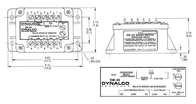
1. Overspeed relay: SPDT, normally energized.
Relay de-energizes and latches on overspeed.
Latching may be inhibited by jumpering Terminal 4 to
Terminal 2; resetting is then automatic.
2. Auxiliary relay: Normally de-energized. Relay
energizes above the setpoint, non-latching (automatic
reset).
Resetting relays:
a. The latched Overspeed relay is reset (after
speed is reduced by at least 2% below setpoint
value) by momentarily jumpering Terminal 4 to
Terminal 2 or by momentarily removing power.
b. The Auxiliary relay will automatically reset when
speed is reduced by at least 2% below setpoint
value.
Power up considerations: No relay flicker on power
up. At stand-still or speeds below setpoints, applying
dc power causes no flicker or change in the normally
de-energized Auxiliary relay. Power application resets
the Overspeed relay to the normally energized (no
alarm) condition.
Grounding, phase referencing: All circuits are
isolated from earth ground. The input circuit is
referenced to the negative side of the power supply so
that the magnetic pickup can be paralleled with
electrical governors and other similarly constructed
devices.
Signal cable shield: can be grounded directly or
taken to any designated electrical terminal on the
governor. (No shield terminal is provided in the speed
switch.)
Test: Jumpering Terminal 5 to Terminal 2 lowers the
setpoints to 90% ±2% of the actual value to permit
verifying the alarm setpoints without overspeeding
the engine.
Stability of setpoints:
a. Signal amplitude effect: ±0.5% full- scale
from 150 mVrms to 100 Vrms.
b. Power supply voltage effect: ±0.1% of
full-scale with 25% supply fluctuation.
c. Temperature effect: ±2.5% of full-scale
maximum with change in enviromental
temperature from –40oC to +85oC (–40oF to
+185oF).
Hysteresis: 2% of full-scale frequency, nominal.
|